
Every so often, I get contacted by someone interested in an rebuild of a Transformer Coupled Microphone such as an MXL2001 or Sterling/Groove Tube ST/GT55. My only solution has been to put a mic parts kit in those mics. This is by no means a bad solution. I’ve built a T84-55 kit from Mic Parts for my own ST55 a while back and the results are fantastic. The idea behind that kit and several other similar DIY project kits is to use the circuit and transformer from a Neumann KM84 in a large diaphragm mic (hence the “T84” in the kit name). The KM84 is an early phantom powered small diaphragm condenser (SDC) mic with an incredibly simple circuit. Despite that, if you can find a vintage 84, it will cost you four digits to acquire it. The KM series of Neumann mics is named for Klein Mikrofon or “Small Microphone” hence these are all SDC pencil style mics. The schematic for the KM84 is no secret and is incredibly simple. It has to be in order to fit everything in that tiny pencil mic (this is from long before surface mount components came along).

The Audio Path of a KM84 consists of just a few parts: An FET, two capacitors and a transformer. Because there are so few components, each one matters quite a bit. In fact, if you can find a vintage BV107 transformer from an original KM, it will cost you almost as much as the mic! When adapting this circuit to an LDC we get to lose one of those capacitors because the capsule is normally not grounded in an LDC. Therefore the audio path becomes even more minimal! And, because we have more room in an LDC, we can add a few non-audio path things to make the circuit perform better. The short version is that the KM84 circuit makes for an excellent transformer coupled LDC!
Into The Rabbit Hole
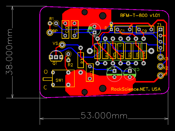
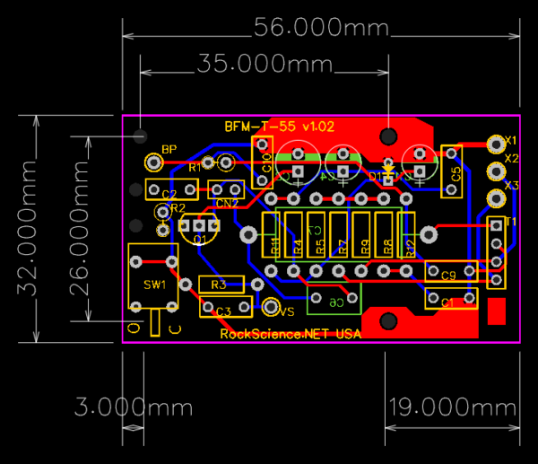
I decided to design my own LDC KM84 style board. I call it the “BFM” because this is for a BIG F’n Microphone, not a Klein Mikrofon. I’ve made two footprints of the board: One that will fit the Sterling/Groove Tube ST/GT55 and another “800” shaped board that will fit most low cost MXL bodies. The boards are called the BFM-T-55 and BFM-T-800 respectively. The T-55 will support the Pad and HPF switches on the Sterling/Groove Tube mic. Both the T-55 and T-800 versions have an optional internal pattern switch to allow switching into Omni Mode.
That Capacitor
The one capacitor in the audio path has to be a pretty big one. The 7:1 transformer is going to nominally present about a 10k Input Impedance to the FET stage so we’re going to need at least a 1.0uF cap to ensure a flat response down to 20Hz. That may not sound huge, but it wants to be a very high quality film cap and they start to get big and pricy at that value. Mic parts uses a Sonicap product which costs about $10.00! Being a bit of a Capacitor Skeptic myself, I couldn’t bring myself to spending ten bucks on a 1uF cap. I opted instead for a $3.09 ‘FastCap‘ from Solen. They say “France” on them so they must be good.
The Problem With Transformers
The only thing hard about building Transformer Coupled Mics is… getting transformers. The high-end goto for transformers these days is Cinemag. Their CM5722w is ideal for this circuit as it is a pretty faithful recreation of the original BV107. However, actually acquiring one of these mythical transformers has proven to be difficult.
The Mic Parts kit comes with a transformer which they have custom wound for them. I do not have such clout, so I’m out trying to score a seven-ish to one microphone output transformer. For my testing and development, I bought a 10:1 transformer from Analog Classics. It’s about $45 compared to about $80 for the Cinemag. I also bought a 7:1 Chinese transformer for about $22. These are in endless easy supply so it would be nice if it doesn’t turn out to be awful.

To The Bench
I had enough parts and bare boards to build a couple of prototypes. I also had to come up with some way of determining the ideal value for the FET bias resistor (R3) for each individual mic. FET Bias is extremely critical in this circuit! I purchased a 20K Bournes Precision 10-turn pot and mounted it in a box with some wires that can be clipped into the circuit. The trick is to determine the value that yields the lowest harmonic distortion, best gain and most symmetrical clipping. Next, I read the actual value of the pot and install a low-noise fixed resistor that is as close as possible to the pot. This has to be done individually for each mic (each FET actually).

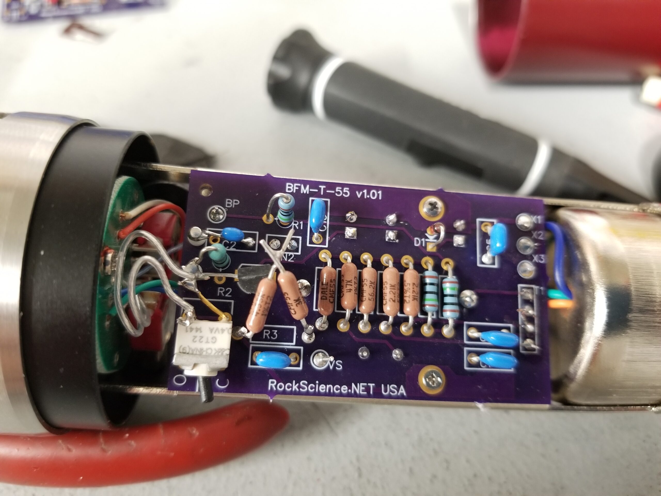
I use REW (Room EQ Wizard for the THD analysis). So you dial it in with the pot and then measure the actual value that got you the goods. For the first two mics, I came up with 7K7 and 8K1 for the R3 resistor values. I didn’t have those exact values in low-noise Vishay/Dale resistors, so I put a couple in series to get close enough for now (I’ve since ordered a whole series of Vishay/Dale resistors between 5K and 8K.


First Tests
After my prototyping phase, I had three mics to work with:
- Sterling Audio ST55 with Mic Parts board and Transformer
- Another Sterling Audio ST55 with my BFM board and an Analog Classics 10:1 transformer
- A prototype BM800 body with the Chinese T-8 Transformer.
The first thing I did was fire up REW and did a sanity test comparing my two builds with the Mic Parts kit just to see if we’re in the same ballpark. We are. The Sterling with the 10:1 Analog Classics Tranny had a significantly lower output than the Mic Parts mic. I expected it to be lower but not by the 6.5dB that it was. Oh well it still had plenty of gain and great signal to noise ratio. The 800 with the Chinese transformer was within a half dB of sensitivity to the Mic Parts mic.
Next, I set up a shootout rig with the Mic Parts ST55 as the compare-to mic and one of my prototypes under it. They both went into identical CAPI vp312 preamps. My main interest is to evaluate the two transformers I have managed to acquire against the Mic parts mic. Apart from that, we are using the same FET, similar Capsules and the circuit is pretty close to that of the original KM84.

I recorded some acoustic guitar with various combinations and took some time to listen to the result. To be fair, we’re comparing several components here: Capsule, Transformer primarily but also FET and ok sure… that fancy capacitor. I printed the MP ST55 against each of the prototypes. That Chinese capsule that I was supposed to hate so much actually turned out quite nice. In fact, I went back to the bench and swapped it into my Sterling ST55 and recorded some more. Here is a short loop of that recording. I am switching mics on every CM7-Em. The entire sequence of three mics happens twice. I won’t say which is which, but suffice to say, I don’t think this chinese T-8 Transformer is a compromise at all. But I still really want to get my hands on a Cinemag to try!
The Hi Pass Filter on the Sterling
This took a few tries to get right. There is a balance here because you want the filter to remove low rumble or other unwanted tone from some instruments and voices. But on the other hand, a transformer does all its cool stuff in the low end, so you don’t want to cut too much. After three different capacitors (and two Mouser orders), I settled in on a cap that gives a great Lo Cut for this mic. Here is the in-circuit response with and without the filter

In Part Two, I dive in to comparing a couple different transformers.
Leave a Reply
You must be logged in to post a comment.