Category: Blog

Your blog category

  • On the Down-Low: Building a DIY Studio Subwoofer

    On the Down-Low: Building a DIY Studio Subwoofer

    For years I’ve mixed primarily on a pair of Focal Solo6 monitors.


    I love the clarity and detail. They’re excellent speakers with plenty of low end for near field monitors. In fact, I never felt like I needed a subwoofer. Obviously I had a bit of a blind spot in the lowest octave but it really never caused me to do anything too dumb in the low end on my mixes.

    recording studio

    But lately, I’ve been working on a lot of modern Reggae Music with my band, Noetic Sea. This genre features heavy low-end and I found that on some of my reference mixes, I was going a little bit over the top with the deepest tones of the kick and bass. I would only learn that during the car test which is not the most clinical listening environment. I decided I wanted to eliminate or reduce that blind spot and at least get another half octave or so in the studio below where the Solo6 monitors naturally begin to roll off.

    More Rumblings of Change

    The second clue came from a couple of outdoor live recordings of my band.

    The recordings were made from the front-of-house mix and supplemented with a stereo room capture using the built-in X-Y microphones on a Tascam DR-40 (without a windscreen). A small amount of wind created significant low-frequency rumble.

    Back in the studio, I applied filtering and thought I had removed it but out in the car, there was still a massive amount of rumble… way down there.
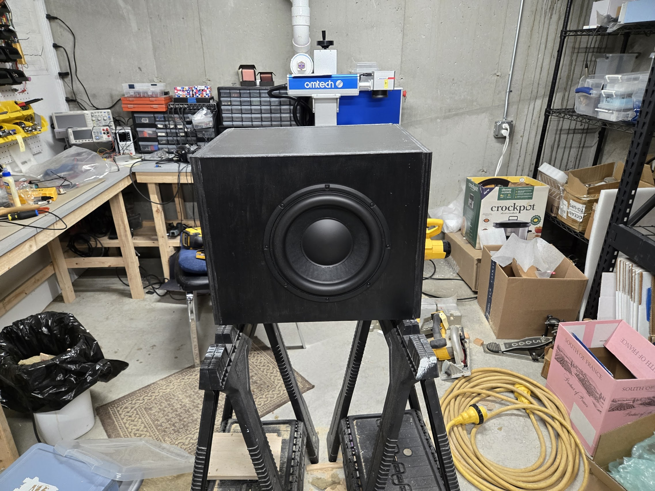
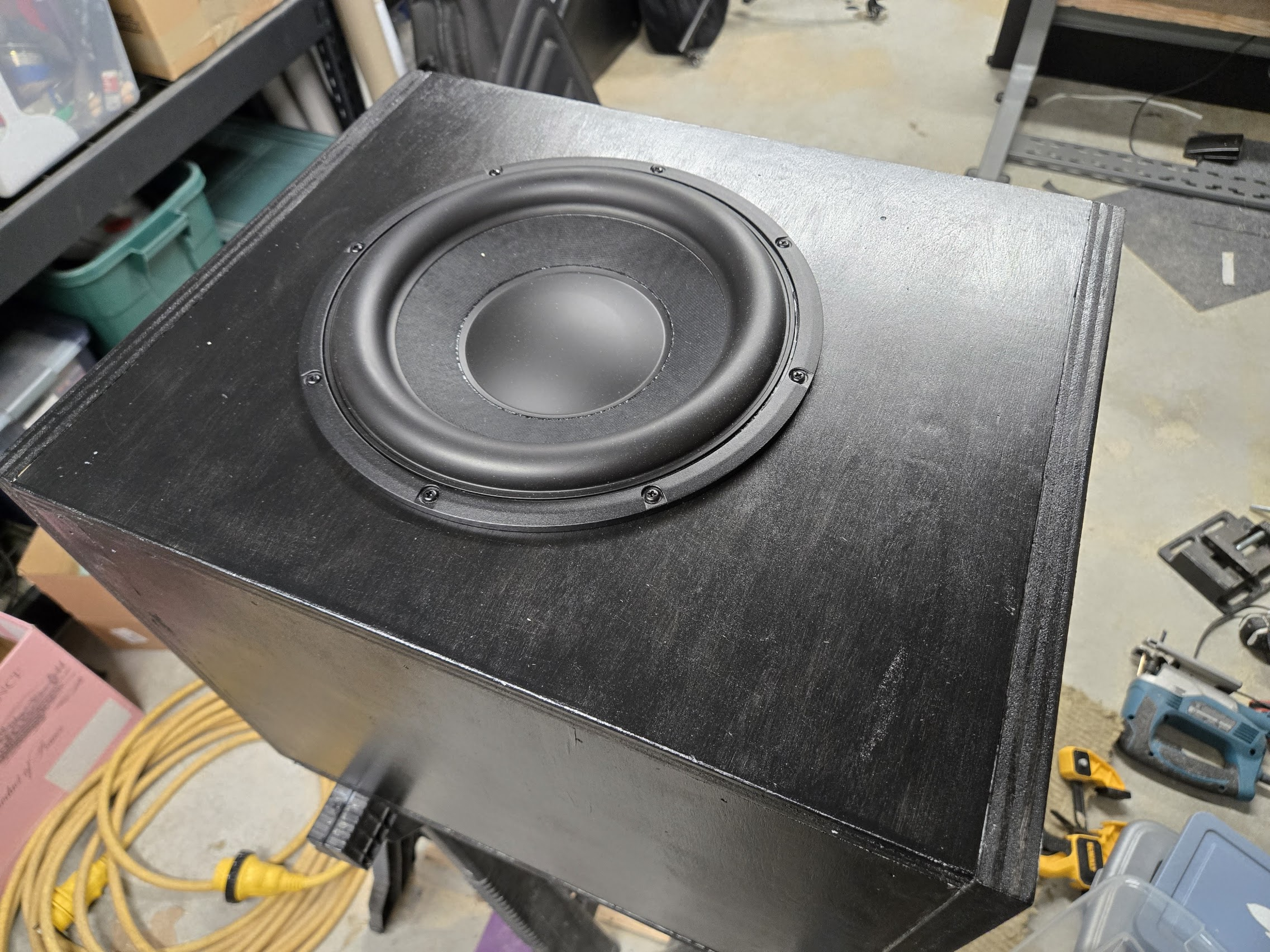
    Subwoofer Painted

    DIY Subwoofer – Design Goals

    I wasn’t looking for a subwoofer that would shake the room or impress clients. I wanted a subwoofer that would subtly extend the response of the Solo6 monitors a little further into the bottom octave while remaining essentially invisible.

    This project documents the design and construction of a compact sealed subwoofer built around a Peerless XXLS 10″ driver and a DSP-powered plate amplifier.

    My priorities were:

    • Small footprint
    • Sealed enclosure
    • Musical rather than theatrical
    • Very low crossover frequency
    • DSP control
    • Clean integration with the existing monitors
    • Ability to design and build it so I could learn something and have an interesting project.

    Enclosure Design

    The enclosure was designed as a sealed cabinet with approximately 37 liters of internal volume. The external dimensions are 17″ ร— 15″ ร— 14″. The speaker is front facing. Simple.

    Why sealed?

    A sealed box provides:

    • Better transient behavior (not that I care about that in a sub)
    • Simpler construction
    • Much simpler design and avoiding endless trial and error of tuning a port.

    The downside of a sealed box is efficiency, but per my design goals, I am just looking for a very subtle extension of the focals and since the subwoofer would be crossed over very low, efficiency wasn’t a concern. The upside of not having to deal with the complexities and trial/error of tuning a port far outweighed this. 37 liters of volume gave a decent curve in WinISD. In Hindsight, as long as I was going with 37, I might as well have gone to 43 liters. That would have extended the range only a few Hz but when you’re talking about 30 Hz, a “few” is pretty significant.

    Driver Selection

    After experimenting with several drivers in WinISD, I narrowed the choices to:

    • Dayton RSS265HF
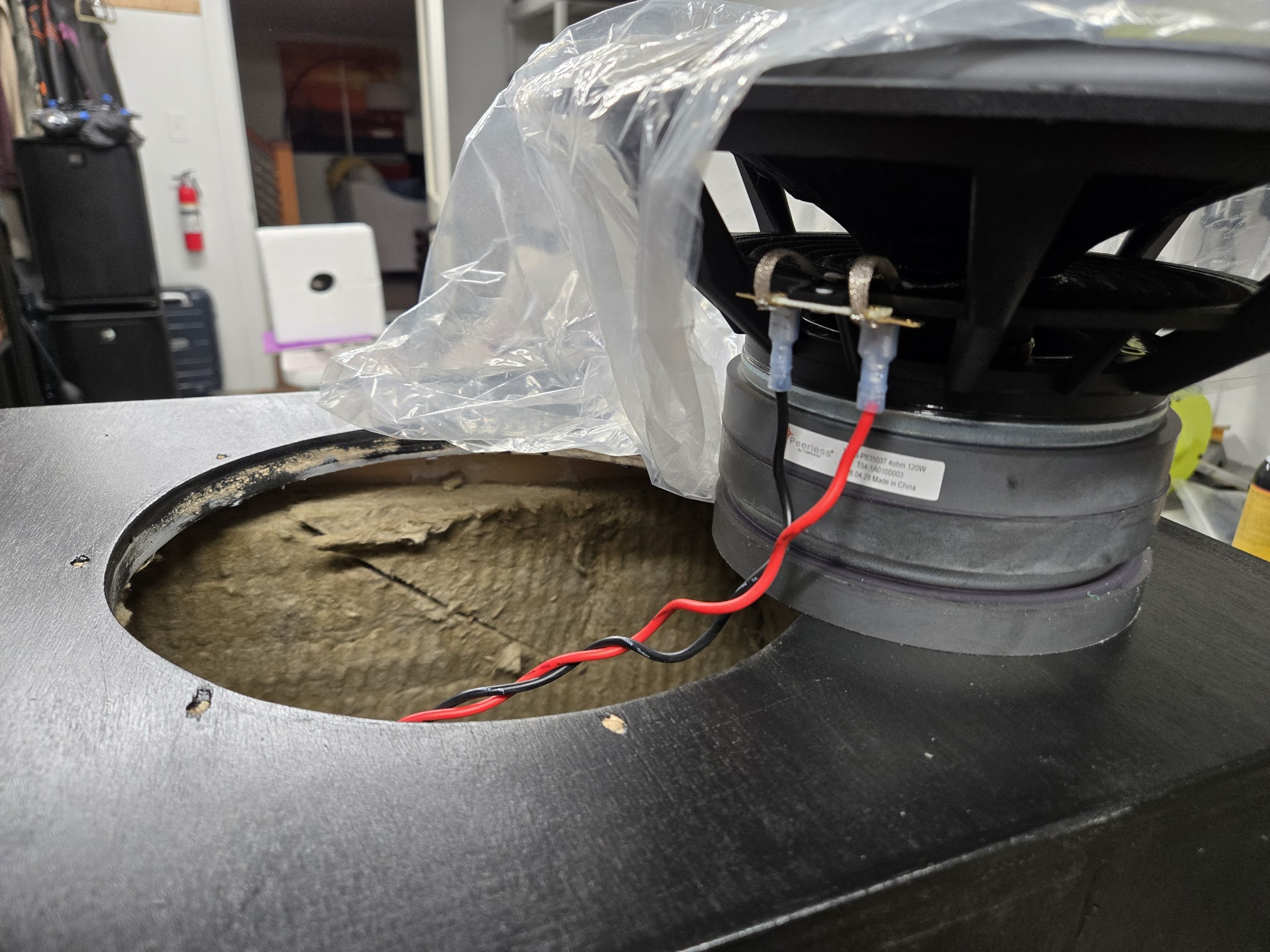
    • Peerless XXLS-P835037

    Either would have worked well, but the Peerless was available from DigiKey for about $111 compared to nearly $200 for the Dayton. I’m cheap like that.

    The Peerless XXLS offered:

    • Excellent reputation
    • Long linear excursion (not that I was going to even come close to the limit of either driver)

    Amplifier

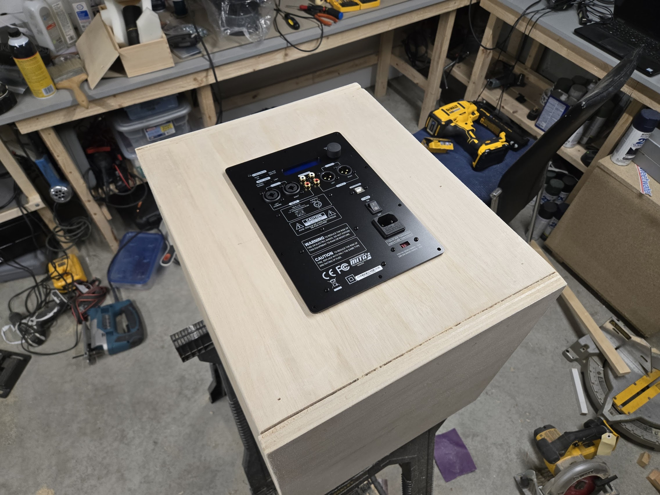
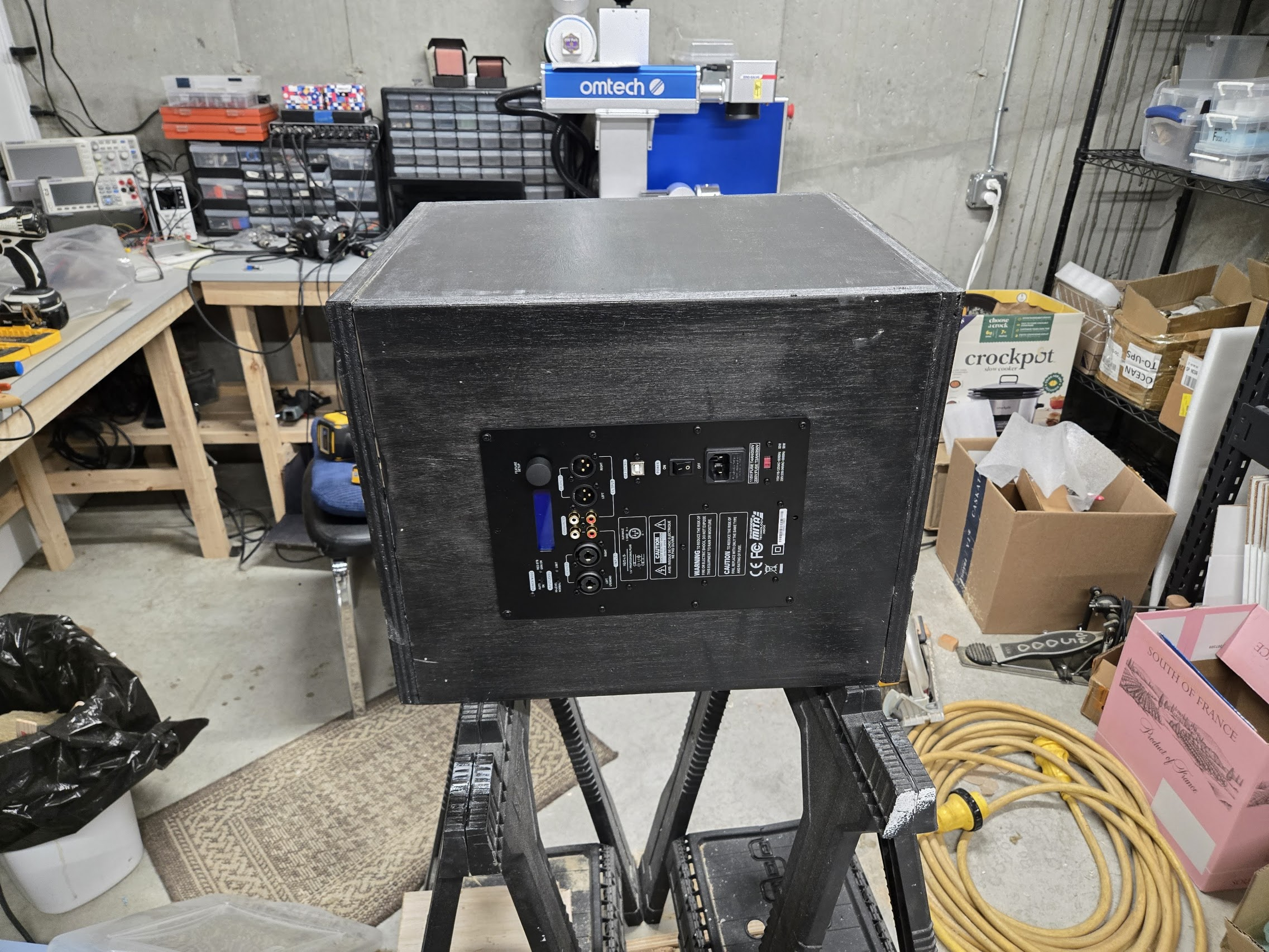
    For the Amplifier, I wanted a plate amplifier with balanced inputs and built-in DSP for setting up filters, etc. The Dayton Audio SPA250DSP was an obvious choice. As of this writing (oct 2026), they are on clearance at parts-express so maybe they won’t be available anymore. It has the power and features I needed and it was about $270.

    The SPA DSP is purpose-built as a subwoofer amplifier. It takes in a stereo balanced signal (xlr or trs), sums it to mono, has some fancy DSP and a twisted pair of wires for the driver. It has built-in DSP for Low and High Pass Filters, Subsonic filter, Parametric EQ and as well as other delay and phase parameters. There is as USB port for programming it with a GUI but I had no luck getting that to work. Fortunately, there is a rotary encoder and LCD display that lets you easily program and store anything you need.

    What I found interesting (as in disappointing) is that the High Pass filter had a minimum fc of 30Hz. The “subsonic” filter only goes to 25Hz (I wanted 10). More on this below.

    Cabinet Construction
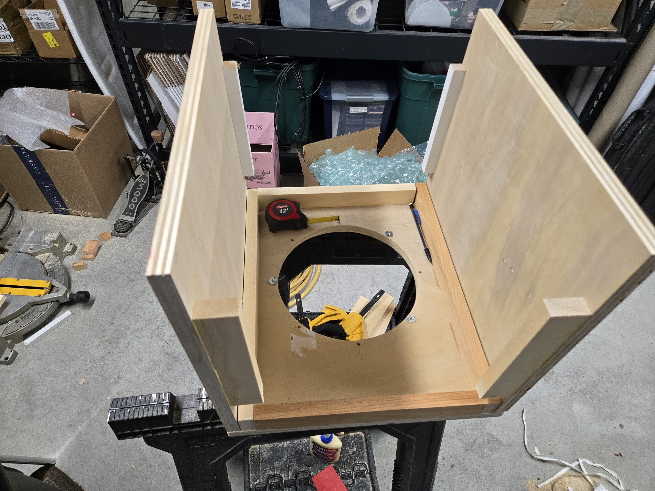
    subwoofer cabinet build
    First Test fittings of the pieces

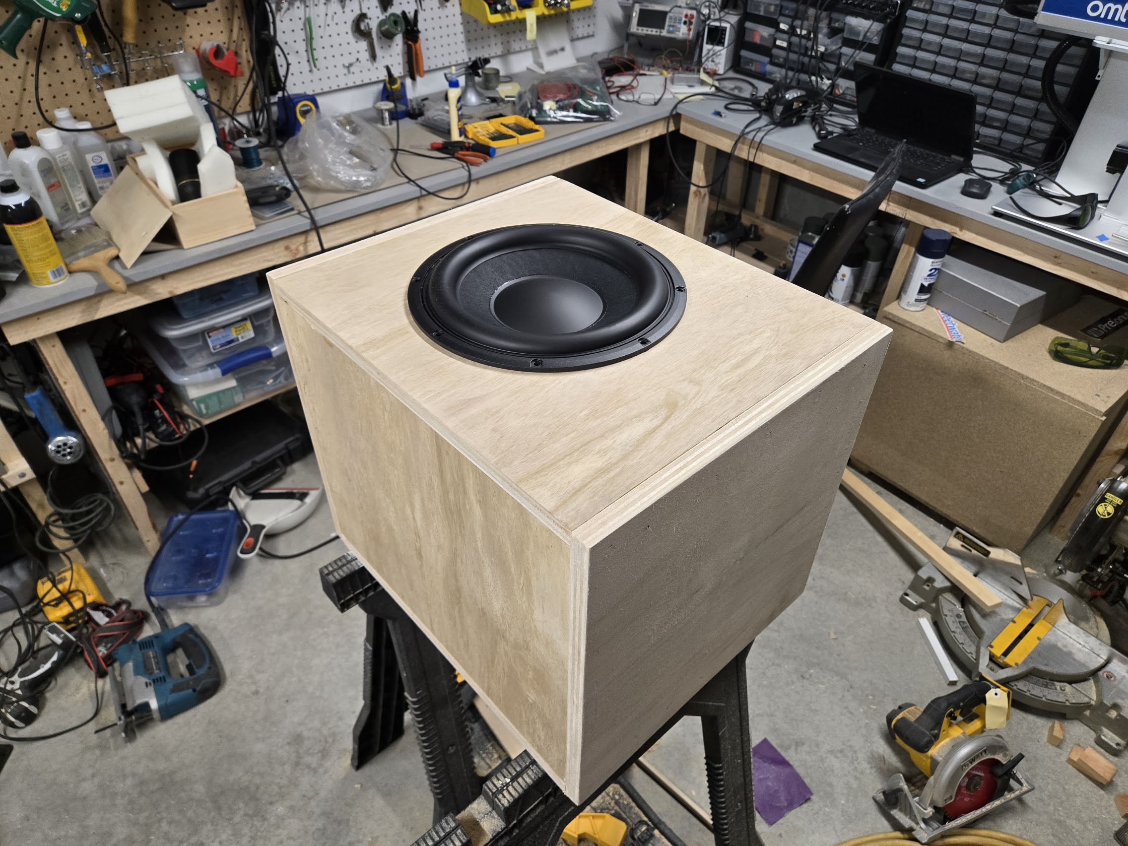
    This cabinet was built out of 3/4″ birch plywood using fairly basic woodworking tools.

    I don’t own a table saw.

    All straight cuts were made using a circular saw and a straight-edge cutting guide

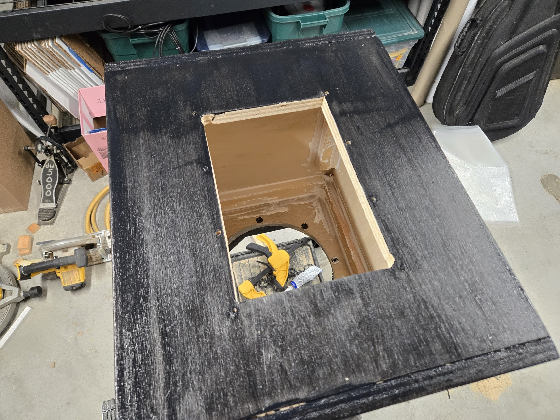
    The driver opening and plate-amp opening were cut using a jigsaw.

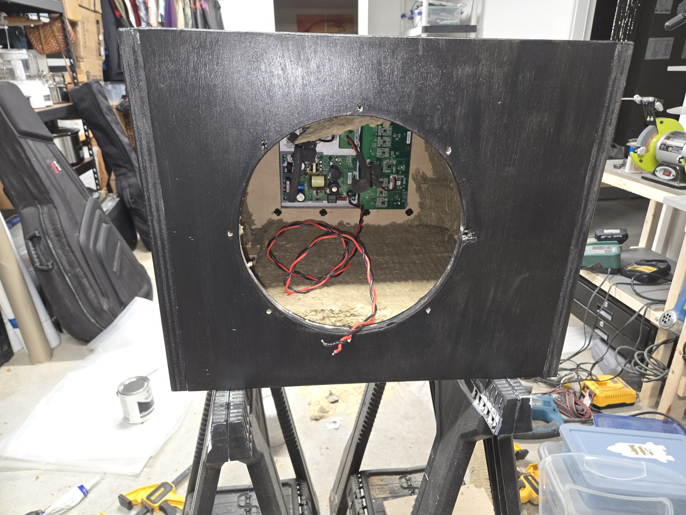
    The driver and amplifier were fastened in with M4 tee nuts and Phillips screws

    The cabinet panels were glued together with internal corner supports and secured using an electric brad nail gun.

    I’m a hack. My goal wasn’t a furniture-grade showpiece. My goal was a functional studio tool. Besides, it is mostly hidden under my studio desk anyway.

    Parts List

    • Peerless XXLS-P835037 Driver
    • Dayton SPA250DSP Amplifier
    • 3/4″ Birch Plywood (2 2×4 sheets were enough)
    • Rockwool or similar Insulation
    • M4 Tee Nuts
    • M4 Screws 8mm length
    • Wood Glue
    • Wood Fasteners

    The finished enclosure came out far better than I expected and looks completely at home in the studio.
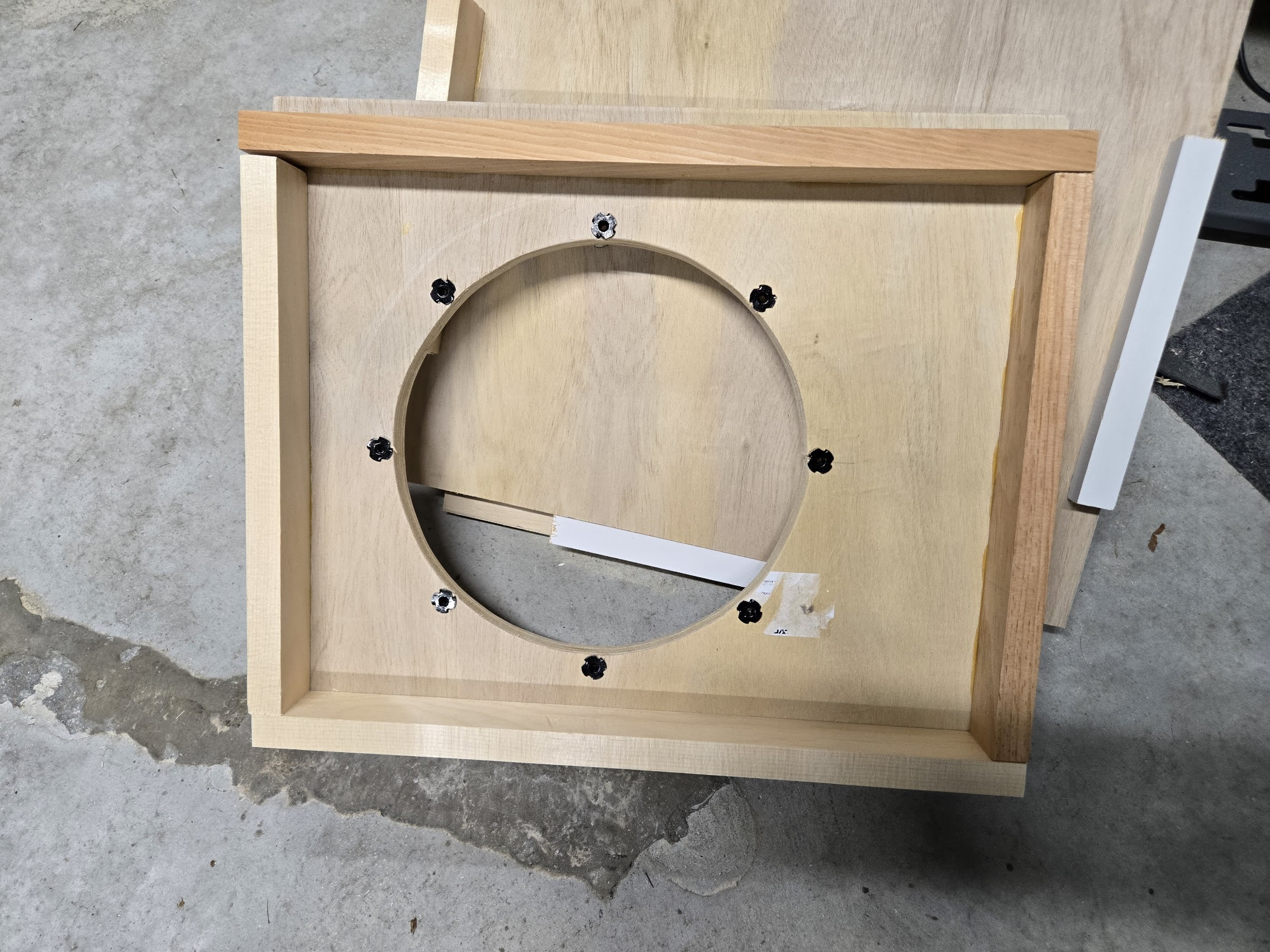
    Internal Construction

    The enclosure is fully sealed and lined with Rockwool damping material.

    The cabinet volume was chosen based on modeling for the selected driver, resulting in a compact enclosure with smooth low-frequency extension and excellent integration with the main monitors.

    I did not put a stiffening “window brace” in this cabinet as my AI overlord suggested. It would have theoretically damped the box resonance, but it also would have robbed me of some internal volume (and been a bit of a pain to do). In operation, the box feels incredibly “still” and stiff so I think it’s fine for this size enclosure. If I went much bigger, I would probably stiffen it.

    The Result

    The most interesting thing about the finished subwoofer is that it doesn’t really call attention to itself.

    The Focals still sound like Focals.

    I use the Dangerous Music M-Box+ monitor switcher which allows switching in a sub. Turning it on gives the focals just a tiny extra something down there that sounds really nice.

    When the low end is over the top in the car, it’s now over the top in the mix room too.

    That’s exactly what I was hoping to achieve.
    Studio Subwoofer
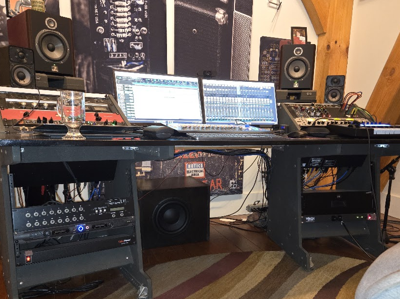
    My partially hidden sub blocking the view of The Who album art on my sound panel

    Listening Impressions

    The biggest success of the project is that the subwoofer doesn’t sound like a subwoofer.

    The Solo6 monitors already provide excellent bass. What the sub adds is a sense of scale and weight in the lowest frequencies.

    The deepest tones of the kick and bass can be judged much more accurately now.

    Most importantly, my monitors still sound like the Focals I know and love.

    Cone excursion is well within the 19mm max specified for the Peerless – even at higher than normal listening levels. I’m definitely well within the design limits of the amplifier and driver.


    Measurements

    I set up REW with my dbx reference mic to do some tests.

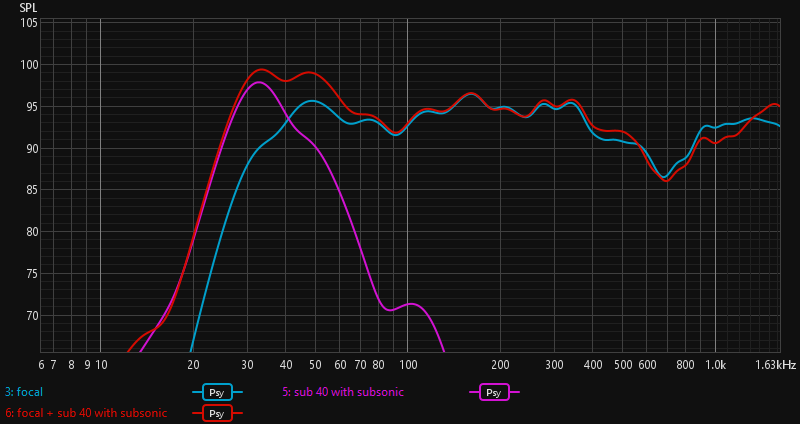
    The graph below shows the low-frequency response of the Focals alone (blue), the subwoofer alone (purple), and the combined system (red).

    Yes, there is a little hump now at the bottom of the Focal’s range, but you can clearly see the extension of about half an octave with the sub engaged.

    The exact shape of the room response is less important than the fact that the sub extends the system by approximately half an octave while remaining well integrated with the Solo6 monitors
    REW Plot studio room

    The Amplifier is set up with a Lo Pass filter at 40Hz with a 24db/Oct slope. I have adjusted the relative volume of the sub to taste and I’m sure I’ll still be tweaking as I do more mixes with this system. My design in WinISD dictated a Hi Pass filter at 10Hz but it turns out that this is not possible with the Dayton amp. The HiPass only goes down to 30. It also has a subsonic filter, but that has a minimum frequency of 25Hz. This seems a bit strange for a purpose built subwoofer amp. I ended up switching on the subsonic filter at 25Hz with a 12db/Oct rolloff. Without it, the sub had quite a bit more cone excursion and the room response was still above 70db below 10Hz.


    Final Thoughts

    This project started as a small experiment and ended up being one of the most enjoyable DIY audio projects I’ve completed. And it was actually a pretty easy project.

    The final result wasn’t a “cheap subwoofer.” Total cost was about 550 USD plus my very valuable time. There are several good choice one could buy off the shelf in that price range.

    The project achieved exactly what I hoped it would. The goal wasn’t to make the studio sound bass-heavy. The goal was to make low-frequency decisions in the studio translate more reliably to other listening environments.

    For anyone curious about loudspeaker design, DSP, or studio monitoring, a small sealed subwoofer is an excellent entry point into the world of DIY speakers.

  • We Don’t Need No Stinking Badges!

    We Don’t Need No Stinking Badges!

    We have a

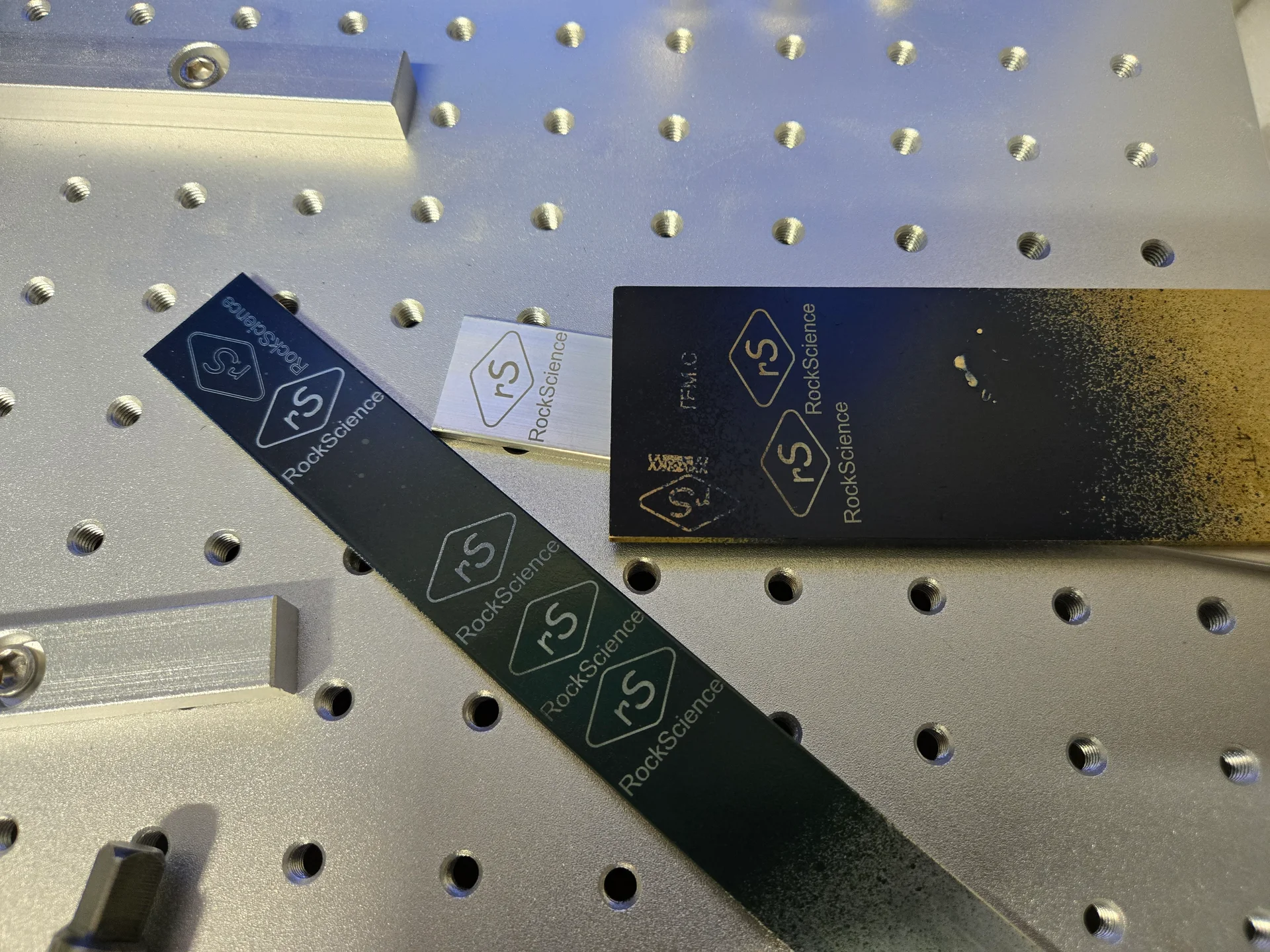
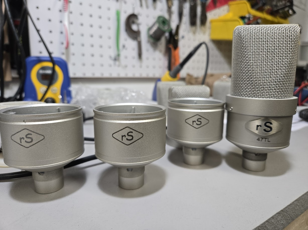
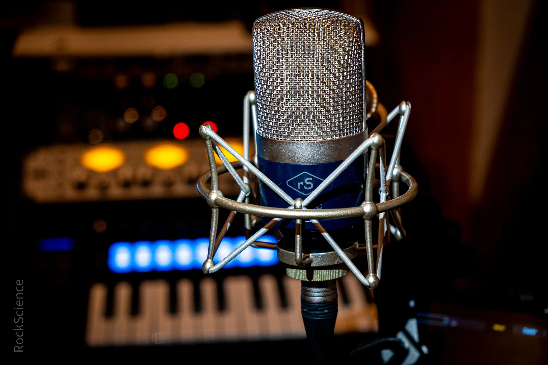
    I used to dress up the mics with with Laser-Cut Nickel Badges. It looked cool. But if I’m honest: it was also the most stressful, anxiety-inducing part of the whole build.

    Bending, aligning, and epoxying badges was a delicate game of โ€œdonโ€™t screw this up.โ€ One slip and the whole mic body had to be stripped or scrapped. I had bending jigs (various PVC Pipe pieces) for each mic body. The trick was to slightly over bend the badge (but not too much). I was spending way too much time playing arts & crafts when what I really wanted to do was focus on the guts.

    Because the gutsโ€”the capsules, transformers, and circuitsโ€”have always been the point. And that hasnโ€™t changed one bit.

    Enter the Laser

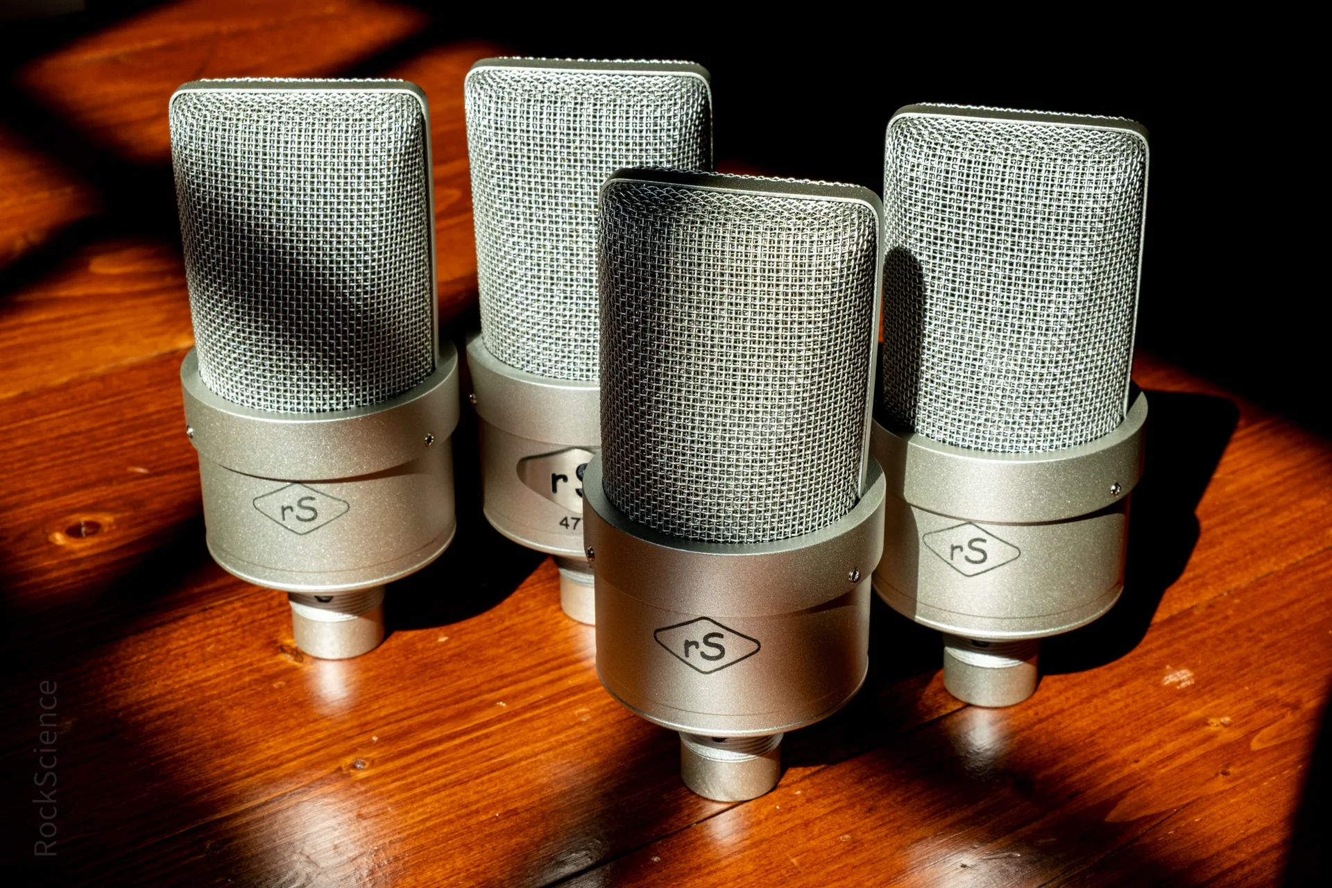
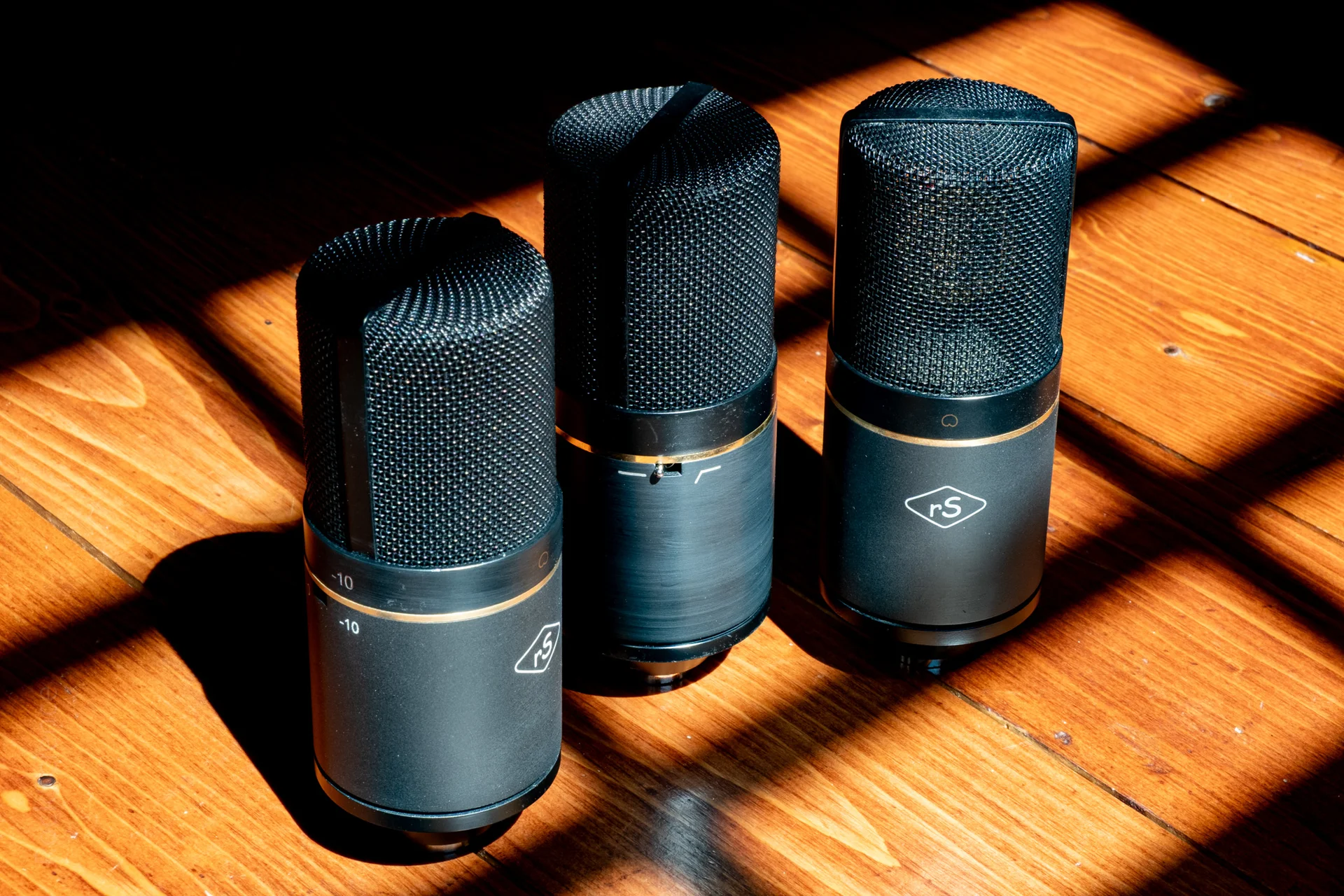
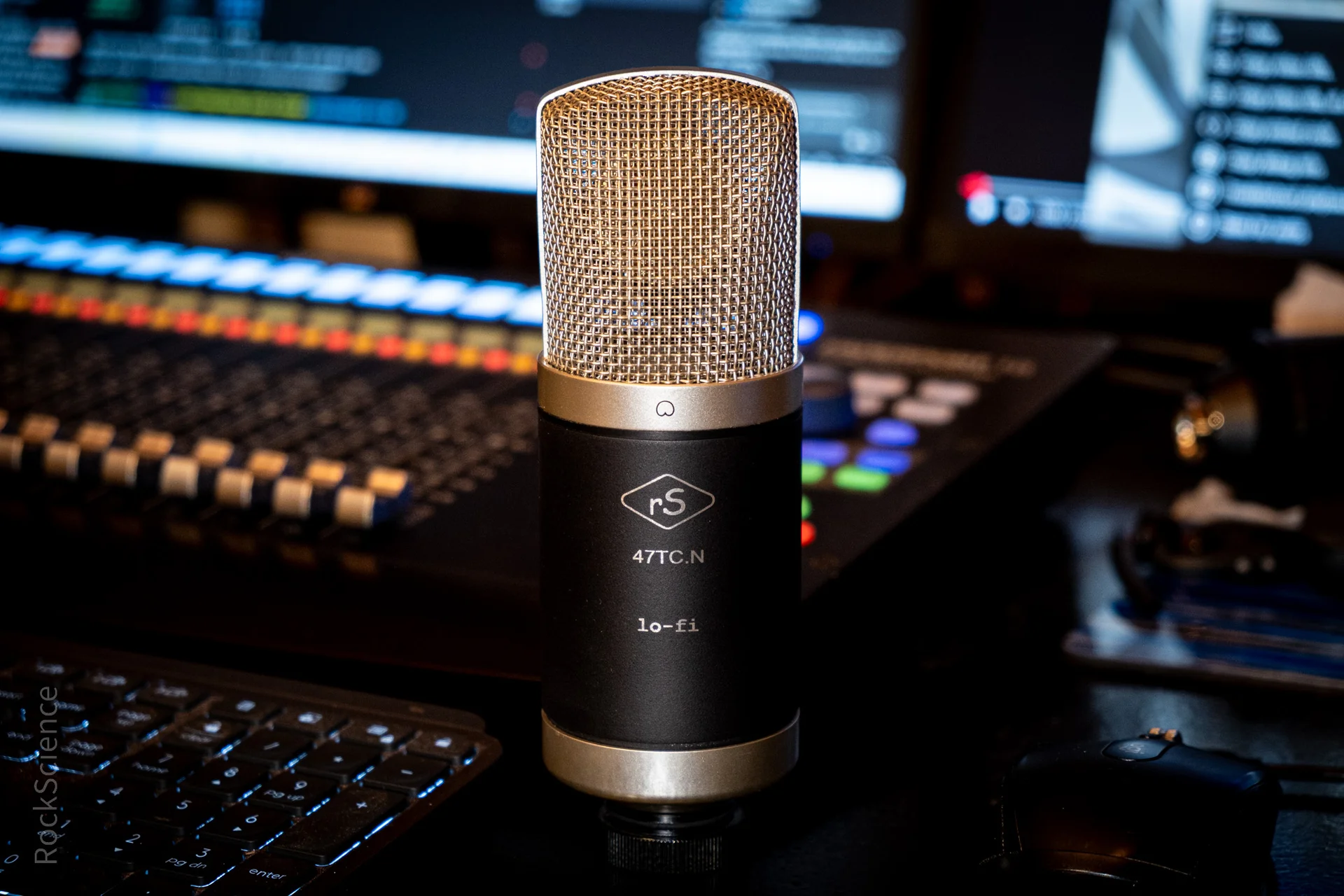
    Starting September 2025, epoxied-on badges are retired. Every RockScience Mic now ships with:

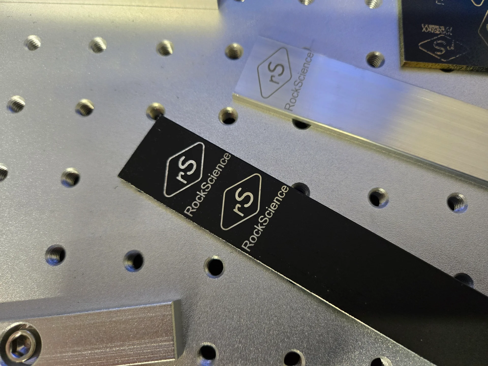
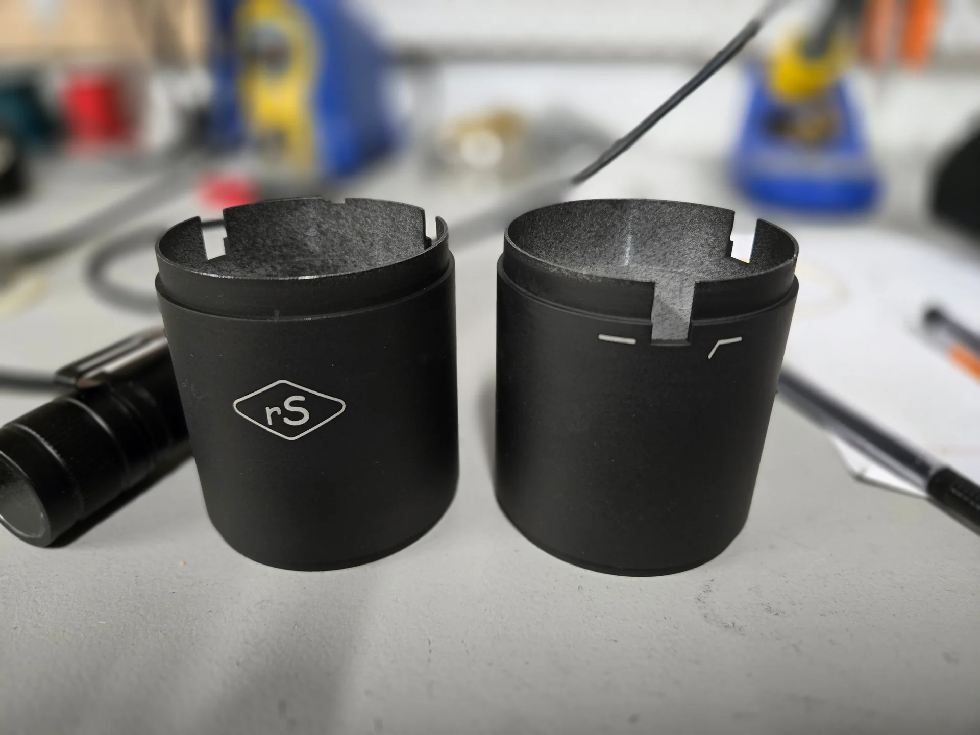
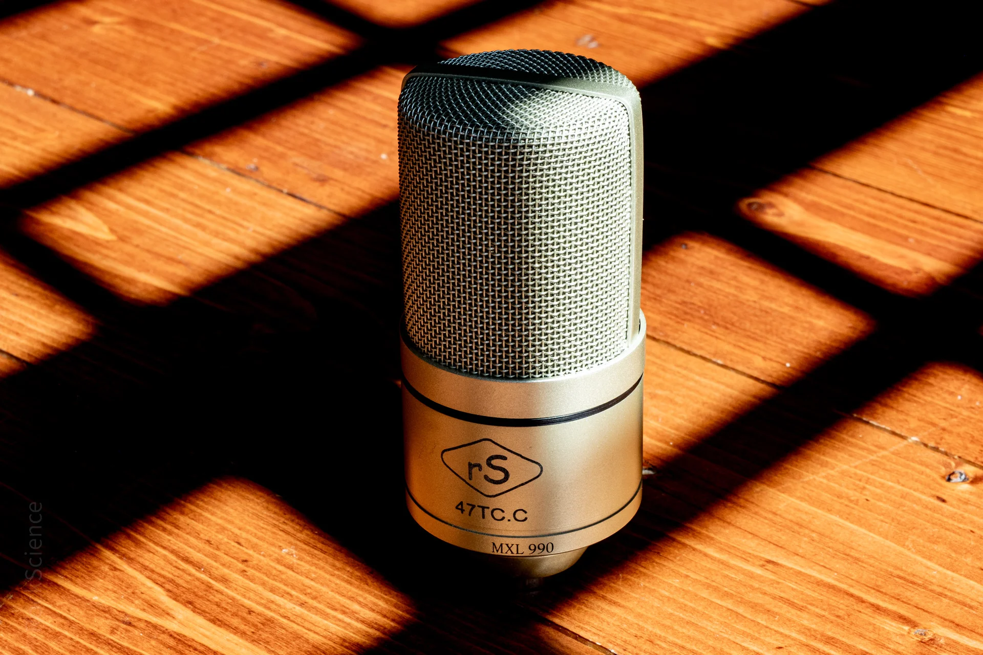
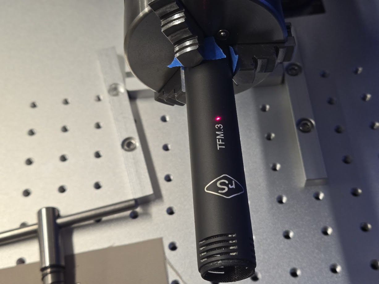
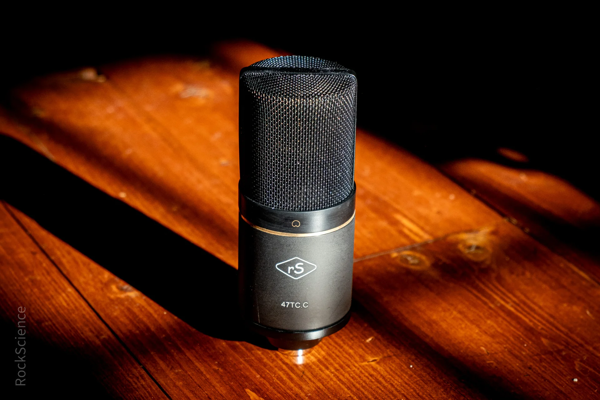
    • A laser-engraved RockScience logo
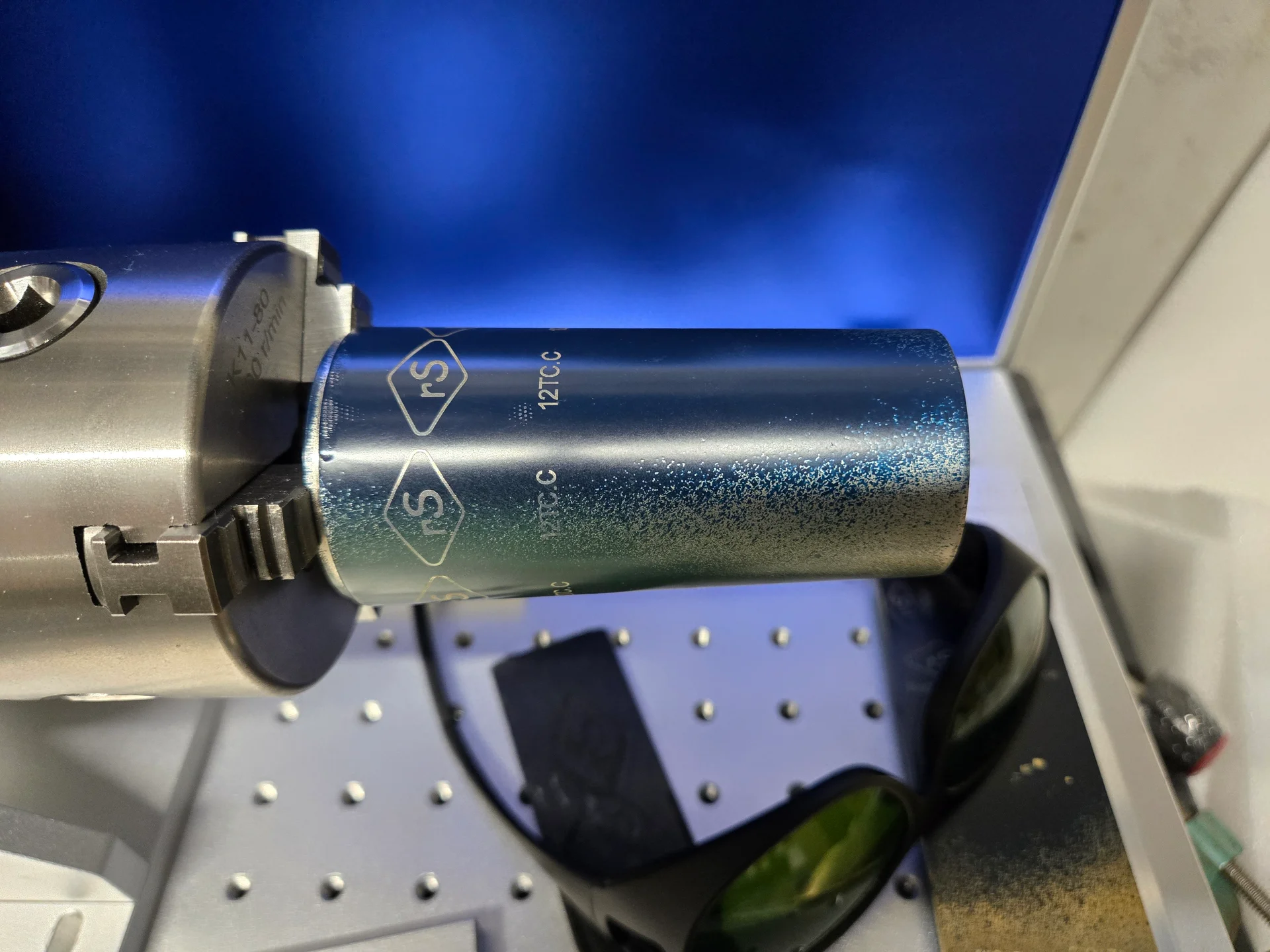
    • A permanent build configuration code, so youโ€™ll always know whatโ€™s inside
    YouTube player

    A short video of an MXL770 Getting the Logo and Switch Icons

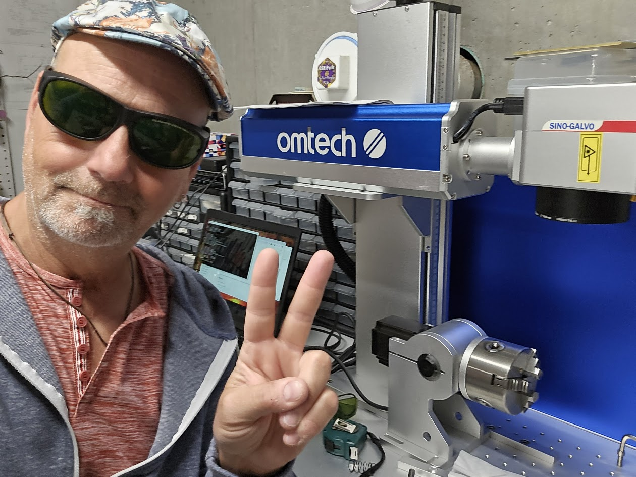
    It took a few ruined mic bodies and hours of testing to dial in laser settings for all the variations of material, color and diameter for all of the mics I work on. But now the process is clean, precise, and consistent. And yes, I look very relaxed in my green safety glasses standing next to the Omtech galvo fiber laser. Those “mistakes” will most likely end up in my mic locker – the same way the mechanic always has the most beat up car.

    Omtech Galvo Laser
    Is that a peace sign or 1/2 Air quotes? Can it be both?

    I spent time dialing in laser settings for black, blue, green paint on aluminum and brass – as well as settings for bare metal for aluminum and brass and anodized aluminum. For most of this, I used scrap pieces of metal to work out the settings. The laser reacts to all of these very differently so it’s a matter of tweaking the power, speed, frequency and number of passes for each variation.

    YouTube player
    YouTube player

    That’s good TV right there


    The Build Config Codes

    This is actually the coolest part for me. I can’t tell you how many times I’ve had to open up a body during a session to remember which mic had which transformer or which was a TL, etc.

    The format is

    [CAPSULE][CIRCUIT].[VARIATION]

    Section Code Meaning
    Capsule Type 47 K47-style capsule
    12 CK12-style capsule
    Electronics TL Transformerless
    TC Transformer-coupled
    Transformer Variation C Cinemag
    A AMI
    3 3U Audio
    N Neutrik (lo-fi)

    Examples:
    12TC.A โ†’ CK12 capsule, transformer-coupled with AMI
    47TL โ†’ K47 capsule, transformerless
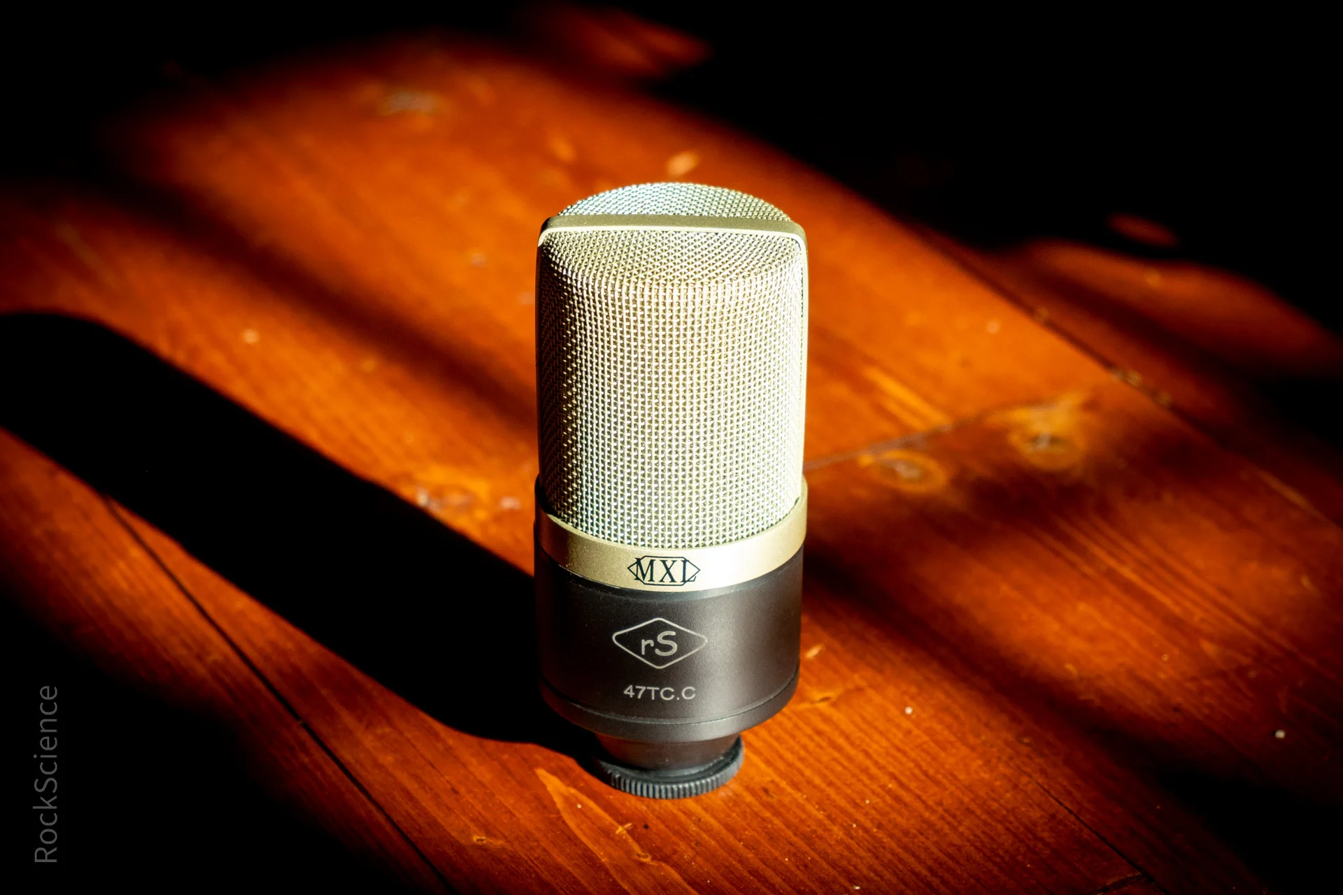
    47TC.C โ†’ K47 capsule, transformer-coupled with Cinemag


    About the Finish

    I’ve got the laser looking great on Black, Blue, Green and bare metal. For the painted surfaces, the black shows the graphics with the most contrast – especially on aluminum mic bodies. For black anodized bodies like the 770, I’m suggesting sanding and applying a finish coat of the flat black (this covers up the usually dinged-up switch logos anyway). The laser cuts through the paint and the anodizing and it looks great. The blue seems to work about as well as the black. Green took a bit longer to dial in because it seemed to need a bit more power – but too much power and the metal underneath gets dull. It’s a balance.

    No more Red. Red was always a problem color. It always took the longest to dry and cure and it seemed to be the softest and most easily dinged up color. I did one quick experiment with the laser and the results were not exciting. So it’s off the market for now.

    As for bare metal, we need lots of power to really cut some material. To get the engraving to show up well, we have to actually burn the body a little bit. The trick is to do that just enough to show up but not so much that things get fuzzy. Again – lots of time have gone into figuring this out.


    The Guts Havenโ€™t Changed

    This is important: the electronics, capsules, and mods are exactly the same. The only thing thatโ€™s different is how the mic looks on the outside.

    So if you already own a RockScience mod with a badge or paint, donโ€™t worryโ€”youโ€™ve got the same great guts. You just own a piece of RockScience history from the arts & crafts era.

    The future, though? Itโ€™s laser-etched.


    ๐Ÿ”ง Nerd Alert: The Laser

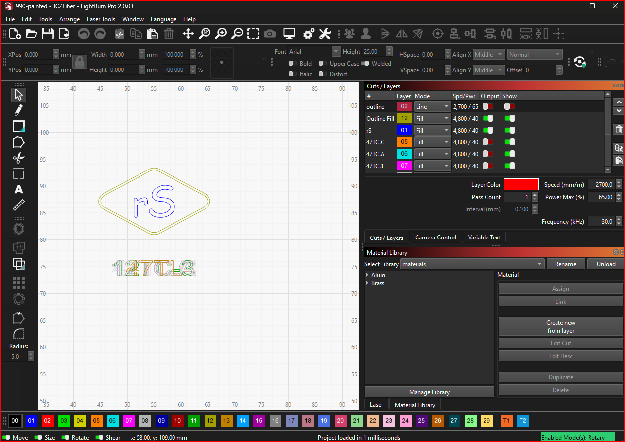
    For those who like to peek behind the curtain: Iโ€™m using an Omtech 20W Galvo Fiber Laser with a Rotary Chuck to do all engravings. Powered by LightBurn, itโ€™s basically the โ€œDAW for lasers.โ€ Settings have to be tuned for each mic bodyโ€™s finish โ€” stainless, brass, painted aluminum. The diameter and taper of each mic body has to be carefully meassured โ€” and Iโ€™ve wrecked more than a few bodies figuring it out.

    Hereโ€™s a little LightBurn screenshot for the curious. This is the file for a painted 990

    Laser For Hire

    I’m not going into the engraving business, but Iโ€™m considering opening up this laser engraving as a service for other DIY-ers. Got a body you want marked with your logo or config? Let me know โ€” if thereโ€™s enough interest, Iโ€™ll make it a thing.

  • MXL 770: Finally it’s a YES

    I never get over feeling excited when an inquiry comes in about a mic rebuild. But a certain number of them turn sad when I realize they are asking about an MXL 770.

    The 770 is an extra tall version of the 990 but the cool thing is that it has switches for Pad and Filter functions. The 770 (like the 990) is a Transformerless Schoeps-style mic with the same (or similar) small capsule as the 990. It also comes with all the same shortcomings.

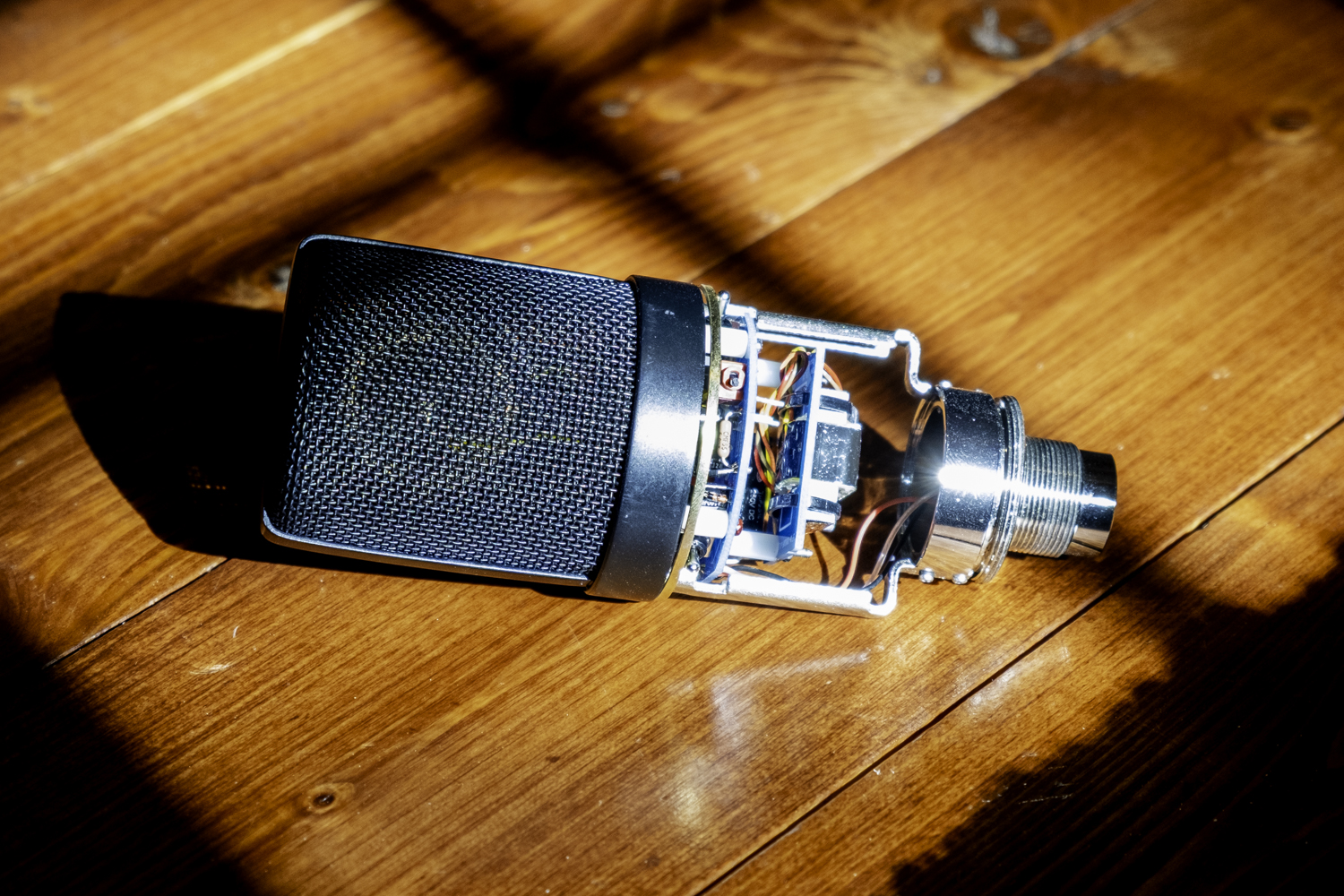
    mxl 770 transformer converted with K47 and cinemag transformer

    I’ve wanted to do a Transformer-Coupled board for the 770 for a long time. There were two technical hurdles to overcome for me to design the board:

    • Sourcing switches that would fit on the board and extend through the body.
    • With all the room that those switches take up, figuring out where to put the transformer.
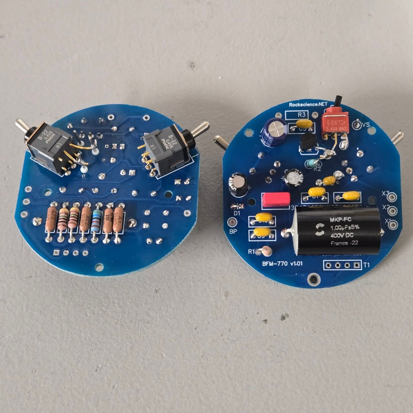
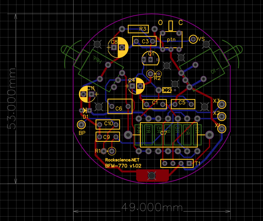
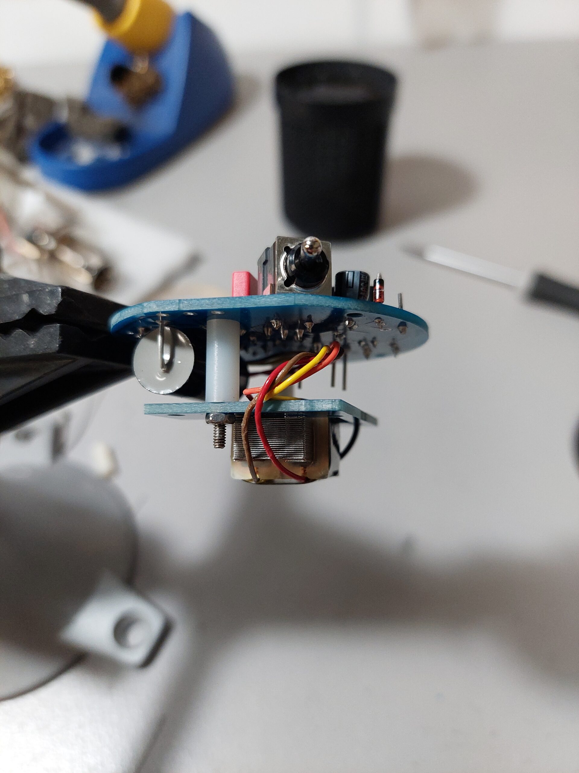
    Both sides of the BFM770. The pad and filter switches line up with the holes in the body

    Fitting it all in

    Since the 770 does not have a separate switch board like the Sterling ST55 or MXL 5000, it’s necessary to fit both external switches on the main board with all the other parts. Of course, I also wanted room for the optional pattern switch. The problem is that those switches take up a lot of real estate. The solution was to mount the switches on the bottom and most of the other parts on the top. But that still leaves no where to fit the transformer.

    some tweaks for v1.02 after the initial run. This is ready for production.

    Transformer Daughter Board

    Fortunately, the transformer mounting board that I already had for other common mics fits in the space and already has mounting holes for some stand-offs.

    Production Ready

    The 770 is now fully supported and available for rebuilds (your mic) or pre-mods (my mic) in the store. I’ve managed to find a few bodies on ebay and have built a few up in various configurations. One of them is now my new favorite in the studio for vocals. I am pretty sure that all this will work with a 990-s (s for “switch”) and the 990 “patriot” which also has switches. I’ll keep my eye out for donors and try it out.

  • Transforming the MXL 5000: A RockScience BFM Rebuild with Custom PCB & Transformer Options

    Transforming the MXL 5000: A RockScience BFM Rebuild with Custom PCB & Transformer Options

    Introduction

    The MXL 5000 is a sleeper hit in the world of affordable large-diaphragm condensers. With a sturdy metal body, a well-designed headbasket, andโ€”unlike many budget micsโ€”built-in pad and high-pass filter switches, itโ€™s already a solid contender. But what if we could elevate it even further?
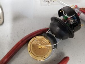
    Iโ€™ve been refining the BFM (Big F’m Microphone) circuit, a design inspired by the Neumann KM84, and now Iโ€™m bringing it to the MXL 5000. This isnโ€™t just a component swapโ€”itโ€™s a complete circuit replacement, featuring transformer-coupled output and a custom PCB that fully utilizes the micโ€™s existing pad and filter switches!

    mxl 5000 mod
    The BFM-5000 board

    As usual, I’m offering multiple transformer options (Cinemag, Tab-Funkenwerk, or 3U Audio) and your choice of capsule (CK12 or K47 style), allowing you to fine-tune the micโ€™s character to your taste. This board also has the optional internal Pattern switch to select Cardioid or Omni modes. The body must be opened up to access it, but on those occasions when you want an OMNI, it’s nice to have that trick.

    In this post, weโ€™ll break down why this mod takes the MXL 5000 from “good” to studio-grade exceptional.

    mxl 5000 on stand
    Finished 5000 with CK12 style Capsule and AMI Transformer

    Why Modify the MXL 5000?

    The stock MXL 5000 is no slouchโ€”itโ€™s built like a tank, has a decent k67 style capsule and external switches on its TL circuit. But like many budget transformerless mics, it is over-bright, sibilant and harsh.

    Our BFM rebuild addresses key limitations:

    • Transformerless stock circuit โ†’ Now transformer-coupled for added depth, weight, and vintage vibe.
    • Basic FET amplification โ†’ Upgraded with low-noise, hand-selected transistors for better clarity.
    • Generic capacitors/resistors โ†’ Replaced with premium WIMA, polystyrene, and metal film components for improved signal integrity.
    • Capsule flexibility โ†’ Choose between CK12 (bright, open) or K47 (warm, smooth) styles.

    The Circuit: KM84-Inspired BFM Design

    The BFM board is a refined take on the Neumann KM84โ€”a circuit renowned for its balanced midrange, smooth highs, and natural tonality. There is very little in the audio path in that circuit: FET->Capacitor->Transformerโ€”that’s it!

    Transformer Options: Pick Your Flavor

    As usual, you can choose your transformer, each imparting a unique character:

    • Cinemag  โ€“ Clean, detailed, with a slight midrange push.
    • Tab-Funkenwerk  โ€“ Vintage-style warmth, reminiscent of old Telefunken mics.
    • 3U Audio  โ€“ A modern take with a slightly lighter low end.

    This flexibility lets you tailor the mic to your preferred tonal profileโ€”clinical and accurate? Warm and colored?

    Capsule Choices: CK12 vs. K47

    This build allows a choice of two capsule styles, each suited for different applications:

    • CK12-style โ€“ Brighter, more open, with enhanced presence. Great for vocals that need air or acoustic instruments.
    • K47-style โ€“ Warmer, smoother, with a slight low-mid richness. Ideal for darker voices, electric guitars, or bass-heavy sources.

    Component Upgrades: Whatโ€™s Inside?

    A great circuit is only as good as its parts. Hereโ€™s what weโ€™re using to maximize performance in all of our BFM builds:

    • Polystyrene Capacitors โ€“ Critical for clean high-frequency response.
    • Low-noise metal film resistors โ€“ Reducing thermal noise for a blacker background.
    • Selected FETs โ€“ Hand-biased for optimal distortion characteristics.

    Sound Comparison: Stock vs. Modded

    Stock MXL 5000:

    • Decent clarity but can be slightly harsh in the upper mids.
    • Transformerless circuit โ€“ Lacks low-end weight and harmonic richness.
    • Good features (pad/HPF), but the electronics limit its potential.

    RockScience BFM Mod:

    • Smoother, more balanced highs โ€“ No harshness, just detailed air.
    • Transformer-enhanced lows โ€“ Fuller, more controlled low-end.
    • Lower noise floor โ€“ Cleaner signal for critical recordings.
    • More “pro” vibe โ€“ The KM84-inspired circuit adds a touch of vintage Neumann magic.

    Best Uses for the Modded MXL 5000:

    โœ… Vocals (especially with the K47 capsule for warmth)
    โœ… Acoustic Guitar (CK12 for sparkle, K47 for body)
    โœ… Drum Overheads (transformer helps with punch and depth)
    โœ… Kick Drum – with K47 (get your 47FET mojo)
    โœ… Electric Guitar Cabs (K47. The pad handles high SPL with ease)


    Final Thoughts

    The MXL 5000 has always been a solid platform, but with the RockScience BFM treatment, it becomes a true studio workhorse. Whether you want a vintage-voiced vocal mic (Tab-Funkenwerk + K47) or a detailed acoustic instrument mic (Cinemag + CK12), this mod delivers.

    Ready to transform your MXL 5000?
    ๐Ÿ“ฉ Contact us for pricing and lead times.
    ๐Ÿ› ๏ธ Check out our Mod Services page for more details.


    Whatโ€™s Your Dream Mic Combo?

    CK12 + Cinemag for clarity? K47 + Tab-Funkenwerk for vintage warmth? Let us know in the comments!

  • Avoiding Common Issues Taking AWS Certification Exams

    Avoiding Common Issues Taking AWS Certification Exams

    I just sat for the AWS Certified Cloud Architect Exam. And I even passed!

    Pivoting to the software development side of RockScience, Here are some lessons learned around taking AWS Certification exams.

    You’ve spent weeks or months studying and taking practice exams, building your own practice infrastructure and it’s finally time to sit for the exam. The last thing you need right now is a logistical gotcha. Here are some tips to avoid those.

    Call me Robert

    When you sign up for certifications at https://aws.amazon.com/certification/, you will be asked to create a Builder ID. This is where you set up the account for your certifications. This account info is then propagated to Pearson who actually administers the proctored exams.

    When I did this, as usual my browser auto filled me as “Bob” and I just went with it as usual. MISTAKE!!!! The key here is to enter your name exactly as it appears on the identification document you are going to use (drivers license, passport, etc).

    When I took the Cloud Practitioner exam, the proctor didn’t catch the discrepancy between my account name and the name on my license (Robert). I took (and passed) that exam. When it was time to sit for the Solutions Architect exam, the proctor bounced me because of the name mismatch.

    Here’s the problem – if I didn’t already have any exam history, I would have been able to self-serve the name change in my account. But because the first proctor let me slide, the name could no longer be changed without opening a ticket with AWS. What a pain. On the other hand, it gave me more time to study. The issue was sorted within two days (and lots of back and forth), but it was a real hassle. On top of that, not only could I not use the voucher from the first exam to get half off, I had to pay full price again for the exam. So instead of $75, it was $225! I probably could have fought that, but was too exhausted and stressed by then.

    Running the system check

    DO run the system check! You don’t want any surprise on exam day. I suggest setting up your testing area exactly as it will be (I suggest even doing this for the practice exams). Make sure you have power, good internet and your wireless mouse is well charged up. You can’t have multiple monitors. If you have them, take them away so there is only on on the desk. If you are not doing this on a laptop, make sure your webcam wire is long enough that you can walk around your testing area (they will ask you to do this at check in).

    The system test is going to look for applications and services that shouldn’t be running. Things like Dropbox and other sharing apps will be tagged. You need to figure out how to stop them running.

    On a windows 11 laptop, one annoying one is going to be “tabtip.exe”. What the heck is that? It’s the virtual keyboard that pops up when you are using your laptop as a tablet. If you stop that in the task manager, windows re-launches is immediately. Here’s how to stop it. In settings, set this to “Never”. I burned up a few hours figuring this one out.

    Download the system check each time you want to run it!

    An interesting thing about the system check app, is that you download an instance of it for each time you want to run it. If you go to your downloads folder and just rerun the same instance again, it will almost succeed but will mysteriously fail the network check. That wasted a few panic stricken hours the night before my first exam. The key is to just follow the link from your email and download a new instance if you want to run it again.

    Check in Procedure

    This is fairly straightforward. You can start the process 30 minutes before your scheduled exam and if you get through it quickly, you can start the exam early. Take off your watch (see below)

    You are prompted to take photos of your test area, a photo of your ID document and confirm your system settings (again). When you are done with your mobile phone and your ID, you are told told that from then on, you are being recorded and must follow the exam rules – including that you can not leave the field of view of your webcam. Your phone and ID card have to be out of arms reach, but you also may need them again if there is an issue. So when you are done with the phone, put it out of arms reach but in a place where you can get it while staying on camera.

    Follow all the other rules too. Make sure the space is quiet around you. If they hear any voices (yours or anyone else), they will revoke the test. Schedule your test accordingly.

    The Queue and the Greeter

    You will be shown your position in the queue. It’s not unusual to be 10th-ish in the queue but it goes by pretty quick. Soon you will be Up Next! and a popup message from the greeter will say they are going to call you through the computer. You say OK and a voice chat starts. Here is where they ask you to pick up your laptop (or other webcam) and show the whole testing area once again. Then they’ll be asking you to show on the webcam that you are not wearing a watch. I’m sure that soon, you’re going to have to prove that you’re not wearing any kind of “smart” glasses.

    Within a couple minutes, you are in the test. Hopefully you are ready and pass with a great score.

    Learning Tips

    This post is mostly about avoiding logistical issues, but I have some thoughts on how to study for this too. First of all, I highly recommend the Udemy courses and in particular the ones by Stรฉphane Maarek. But it can’t hurt to buy one of the other instructors’ courses too. They are cheap! I bought two courses and I also bought the set of practice exams from Stรฉphane. In total, I had six practice exams. My suggestion is to take the first one without looking up anything (cheating) to get a baseline. If you do great, then great! If you’re like me, you barely passed. For the subsequent exams, I did them as “open book” and I looked up and learned details right then and there for any questions I had doubts about. I think this made a huge difference for me.

    Are the practice exams realistic?

    This is the big question. I passed every single one… until the very last one (the morning of exam day). That one was massively harder than any of the others and I failed it miserably. That gave me a psychological whammy to deal with. For me, the real exam was maybe just slightly easier than the average of the practice exams. But that’s just my impression and I wouldn’t count on it!

    Good Luck! Build something cool! Hire me to help!

  • SDC Mics: Say hello to my little friends

    SDC Mics: Say hello to my little friends

    I’ve been building Transformer Coupled LDC mics for a while now. My BFM (Big F’n Microphone) circuit is adapted from the Neumann KM-84 (kleines Mikrofon – 84) circuit with very minor differences from the original. I have finally gotten round to building some SDC mics with another adaption of the BFM circuit called the TFM (Tiny F’n Microphone).

    sdc mic mod

    Donor Bodies

    Donor bodies are plentiful for these mics. From MXL alone, there are 551, 991 603s and 840 (and maybe more). The 551s and 991s are usually in a set with a 550 or 990 respectively, but sometimes we can find them alone.

    TFM Circuit

    The TFM really is pretty tiny. There is not a lot of wiggle room on the board – especially when a large chunk of the board is taken up by the Transformer. Fortunately the KM48 and our derivation of it is a very simple circuit and within a few revisions of the board, everything is fitting and working out well. As with the LDC bards, the capsule and FET wiring is off board and using Keystone insulated turrets for the point-to-point wiring.

    sdc mic mod km84

    Transformers and Capsules

    I’ve been building my BFM boards with either CineMag or AMI transformers, but will now be offering the 3U GZT-84 Transformer. The tone is slightly brighter than the CineMag or AMI and it it seems to have a bit more harmonic distortion in the low frequencies than the others. And this is largely what gives transformer mics their sound.

    For capsules, I am offering options from 3U Audio. Their capsules come in several polar patterns apart from the standard cardioid and they sound amazing. Because the capsule is easily field-replaceable, you can get several capsules for your mic and swap in the one that is appropriate for what you are trying to capture.

  • New Microphone Footprints Afoot

    New Microphone Footprints Afoot

    Since I’ve been building and rebuilding microphones, I’ve only imported one type of body – the so-called BM800 style body. These are what I’ve been using for the RS/ series mics like the RS/47, RS/12t and RS/47t.

    I’ve been tempted to try some other shapes and sizes that I see on my various suppliers’ websites and I finally acquired a few samples of some new styles. New shapes mean new Circuit Boards and I’ve finished jaSb (just another Schoeps board) transformerless and BFM (Big F’n Microphone) transformer-coupled board designs for both new bodies.

    The Tall Boy Telefunken-ish style

    custom mic build

    When I ordered this thing, the photo didn’t do justice to how huge it is! First impressions are that it’s a nice quality body with a heavy cylinder and a good quality headbasket. The Internal frame is much bigger than a BM-800 style and so the circuit board is nice and big. The jaSb and BFM boards were very easy to design for this mic given all the space. In both cases, all components can fit on one side and in the case of the BFM, there is actually room for the transformer right on the main board!

    The TLM 102 Style

    custom mic build

    I was really excited to find a good source for these. I’ve always loved the look of the “little” Neumanns and I occasionally get asked about rebuilding a TLM mic (or a TLM clone). Until now, I had no circuitry that would fit. The samples arrived and I’m really happy with them. The cylinder is solid and heavy and the headbasket is beautiful.

    In terms of size, this is the extreme opposite of the Tall Boy. These are tiny and the the circuit board layouts were very challenging – especially the transformerless jaSb version which has many more parts.

    Unlike most of my other builds, these mics are not so straightforward to open. The headbasket is fastened to the body with three hex set-screws. For that reason and because of the limited size of the board, I’m not going to fit the optional internal pattern switch in theses. They will be full-time cardioid (or omni if you wanted). The board is round like an MXL 990 but only 47mm in diameter (with some notches cut out) compared to the 53mm diameter of the 990 board. Besides losing the pattern switch, I had to put some components on the bottom side for both boards.

  • Microphone Care

    Microphone Care

    No matter what mics are in your collection, you want to take care of them. No matter how cool or boutique or amazing a mic is, if you go to use it and itโ€™s got a problem, itโ€™s worthless at that moment. I’ve learned a lot from doing the Custom Microphone Mod Shop and I’ll share some of that here.

    mic mods

    Storage

    Mic Cabinet, Mic Shelf, Shoe Boxโ€ฆ Everyone has their own version of the โ€œmic lockerโ€. Besides questions of theft security, the main things you should be worried about here are

    • Moisture
    • Dust
    • Accidental Damage

    Microphones have very sensitive elements. Condensers and Ribbons especially have extremely low mass surfaces which pick up the sound waves. It takes a very small amount of dust and/or moisture to significantly alter this mass and therefore the ability of the element to translate sound pressure into voltage.
    Iโ€™ve had some mics come into my shop for rebuilding and the capsules were actually corroded and pitted from years of being in high moisture environments. And when they get wet, they also get caked with dust.

    Desiccant (Do Not Eat)

    Those little desiccant packets are your friends.  We all get them when we buy junk from Amazon. It does no harm to throw a few of them in where you store your mics. If you are in a high humidity environment (get a Hygrometer to measure), Iโ€™d strongly suggest storing your mics in a room that has a Dehumidifier running. Keeping the capsule dry is probably the single most important thing you can do. 

    Microphone Dominos

    Another obvious tip for storage is to keep the mics in such a way as to avoid accidentally damaging or dropping them. Standing a bunch of mics up on a shelf may look cool, but sooner or later you’re going to knock one over (which will certainly knock the rest over). This, I know first-hand.

    Hot-Plugging

    I see some variation of this question on Facebook all the time.  Is it safe to plug in in a mic with Phantom Power already on?  The other related question is if it is safe to apply Phantom Power to Dynamic or Ribbon Mics (often you donโ€™t have any choice when using low-end mixers with one phantom switch for all channels).

    If everything is working right with Phantom Power, there is an equal voltage potential on pins 2 and 3 with respect to ground (pin 1).  That means there is NO potential across the output transistors or transformer.  The reason there is any question about hot plugging is that unless you can insert the XLR jack at the speed of light, there is going to be some tiny instant of time where pin 2 or pin 3 makes contact before the other. During that time, there IS a potential across the output transistors or transformer.  Notice I said โ€œIf everything is working rightโ€. Having a bad mic cable with pin2 or 3 disconnected or intermittent is going to cause the p48 to be applied across your output device. Maybe it can take it… maybe it can’t.

    Does it matter?

    This is what everyone wants to know. To me itโ€™s like asking if itโ€™s safe to cross the street.  My answer is that it is usually perfectly safe. Transformerless condenser mics (at least all ones that I am familiar with) have protection diodes in the output section to provide protection to the output transistors. Some mics use transistors which can easily tolerate this voltage even without the diodes.  Most transformer-coupled Condenser mics should tolerate this too.

    Bottom line, Iโ€™d avoid hot-plugging, but I wouldnโ€™t worry too much about it.

    Ribbons

    Ribbons are a different animal.  They donโ€™t need phantom power but they may have it applied for one reason or another. You might switch it on by mistake or again, if itโ€™s plugged in with an all-or-nothing type device that puts phantom on all inputs. I have less experience with Ribbons, but I believe it should be ok to have a stable phantom voltage applied (Iโ€™ve certainly done it with no problems). I think it is probably best to avoid hot plugging ribbons and if you canโ€™t avoid having phantom applied, make sure the mic cable is a good one with no intermittent connections.

    Dynamics

    In my experience Dynamic mics are pretty bulletproof. They can tolerate hot plugging (and pounding in nails).

    Shipping/Transporting

    One thing Iโ€™ve learned the hard way over the last year is that Shipping Carriers are very good at wrecking microphones.  The opening scene of โ€œAce Ventura, Pet Detectiveโ€ is probably a bit of an exaggeration but maybe not by much. Large Diaphragm Condenser microphones do not like rapid Deceleration (ie: sudden impact).  The capsule is heavy and typically suspended with a pretty feeble mounting cradle.  Why not make the mounting stronger?  Because the optimal microphone would have NO cradle at all – the capsule would be magically suspended in mid air by some unseen force. Since this technology does not yet exist, we use cradles that are as strong as possible while being as thin as possible. The net result is several broken capsule cradles which were not broken when they left my shop.

    Rode NT2 after UPS got through with it.ย  The capsule cradle broke and the capsule is destroyed.

    When mics come to be for rebuilds, I am often horrified at the packaging. The mics are slamming around inside the box and they are wrapped with one thin layer of bubble wrap (if that).  I generally donโ€™t care because I am typically replacing the entire guts of the mic anyway.

    You canโ€™t prevent careless handling all the way through the chain. I recently shipped a mic to a customer (with six red โ€œFragile!โ€ labels on the box) and watched the clerk toss it onto a pile of boxes about five feet away.  This was at Point A with me watching!  Imagine what happens between point A and B.

    Deceleration

    The best you can hope to do is slow down that rapid deceleration (absorbing the shock) when the mic inevitably gets thrown, dropped, kicked, whatever.  

    Contrary to popular belief, bubble wrap is really not very good at absorbing shock. You want elasticity/cushioning, and bubble wrap doesnโ€™t really offer much of that. Itโ€™s great at taking up space (also important). If you have the original packaging for the mic, it will typically be in some soft cushioning foam. This is what you want. If you donโ€™t have the original foam, I suggest getting some soft shipping foam (1 or 2 inch thick) and wrap the mic in it. You want to absorb shock on all axis  – they might drop it upside down!

    If your only choice is bubble wrap, use a lot of it.  Spend the extra money on the larger package and wrap it in a big fat cocoon!

    Shake Test

    Once closed up, shake the box. There should be NO movement inside the box. This is where bubble wrap and craft paper are valuable. They are great at filling the space so the mic can not move (accelerate / decelerate) inside the box. 

    Crash Test

    After my third customer had a mic arrive with a broken capsule cradle (and an expensive ruined capsule), I upped my packaging game and decided to do a little test. With my latest packaging, I tossed a mic out of the second story window to the pavement below. It survived perfectly.  (Iโ€™d like to point out that this was my microphone, not a customerโ€™s mic).

    Troubleshooting

    Believe it or not, there are not that many things that can go wrong with a mic. Thereโ€™s an element, a circuit and/or transformer and a connector.  Depending on the type of mic, different symptoms can mean different things. 

    A good first step is to make sure the problem IS the mic and not the mic preamp. Plug in a similar type of mic and verify that it does not have the same problem. 

    Hum – 

    Condenser mics are extremely susceptible to hum pickup. Inside that body, they are converting a very weak high impedance signal from a capsule to a signal capable of driving a low impedance input on your mic preamp.  Hum almost always means that the body shielding has lost some integrity. Very often this is simply some oxidation on where the various pieces of the body fasten together.  The idea is to have a very good connection from pin 1 of the XLR through all of the body and headbasket parts.  Itโ€™s usually possible to take the body apart and clean the edges and surfaces. You can even take a scotch brite pad to the edges.  Normally, this will solve the hum.   If the hum continues or is intermittent, it may be that the circuit board is not making a good grounding contact for some reason. This might get a little harder to figure out on your own.

    In the case of Tube mics, another likely culprit is the power supply itself. It probably has a failing filter cap.  One hint to this is if the tone actually sounds more like 120/100Hz rather than 60/50 Hz.  If so, it is definitely a power supply problem because you are hearing full wave rectified AC mains.

    Hiss – 

    In my experience, this is always the result of one of the zener diodes failing in a Condenser Mic. Depending on the design, there is at least one zener for the power supply and additional ones for hot-plugging protection (see above).  Any one of those could be the culprit but in my experience, itโ€™s always been one of the protection diodes. If you have some basic soldering and desoldering skills, these are not hard to replace. The protection diodes are typically 6.2v.  You could also just try removing them (and then be extra careful about hot-plugging).

    Whistle – 

    This is a strange and interesting one.  Many transformerless condenser mics actually have an oscillator in them. This is used to step up the voltage to polarize the capsule.  That oscillator runs at around 2 Megahertz so you should never hear it. But sometimes, a problem with the oscillator circuit can cause it to produce a component in the audio range. Another strange thing that can happen is if some of that oscillator tone leaks into ground, it can cause interference with other mics.  If the two micsโ€™ oscillators are within 20KHz of each other, you may be hearing a difference frequency.

    Low Output – 

    If a condenser mic suddenly has a low output, there are a few possibilities but before we look at the mic, remember the part above about checking the preamp. This could be a problem with low phantom power voltage. Some mics perform very poorly with low p48. I had a Behringer device on my bench that on a good day would only put out about 14 volts! Most of my mics worked ok, but I had an oktava that was totally silent.

    Assuming itโ€™s the mic, this is probably not good news. It might be the capsule itself. If the mic has a pattern switch, flip it to omni mode and see if the output is still low. If not, it probably means that the front diaphragm of the capsule has failed.  Otherwise, weโ€™re into the circuit (or transformer) and this is probably a job for a tech.If a condenser mic has a low output on power-up, give it a minute to warm up. I mean this for non-tube mics too. Some mics (like the Rode NT2) have a very slow charge up time for polarizing the capsule. Until I learned that, I thought I broke a customerโ€™s mic – it was silent on power-up.  The NT2 takes 70 seconds to fully charge the capsule!

  • Microphone Repair

    Microphone Repair

    Sometimes you just want your mic to work again. Our mic mods are really full rebuilds so they are very effective microphone repairs too. No matter what has gone wrong with your mic, chances are the broken bit is being replaced. I often buy “broken – for parts” mics off the interwebs and rebuild them. As long as the body hasn’t been run over by a car (I’ve seen this), the mic can be made whole again and drastically improved over its former stock self.

    studio projects mic mod
    Broken SP C1 mic

    Most (non-tube) mic problems come down to either the capsule or the circuit board. I replace them both so the chances are pretty good that your dead mic will live again. Someone sent me a dead Studio Projects C1 to see what I could do with. In this case, the capsule was damaged and easily replaced. The circuit in that mic is actually pretty good as-is so we left that alone.

    bm800
    Broken BM800 Looking and Sounding Great

    A throw-away cheapo-amazon BM800 came through the door totally non-functional. The board and capsule were junked and we made a lovely transformerless mic with a k47 style capsule which has gone to a good home and gets regular use.

    mxl 990 mod
    Rescued (broken) MXL 990

    MXL 990s seem to get all the abuse. Of all the mics I’ve modded, these seem to come in the most beat up. Whenever I can find one on ebay or reverb being sold as “broken / for parts”, I jump at it. The most recent one became my very first Transformer-Coupled 990 mod. This mic repair has turned into one of my favorite mics in my collection.

  • MXL 990 Microphone Mods

    MXL 990 Microphone Mods

    Depending on who you ask, the MXL 990 is either awful or amazing. I have mixed feelings about these mics. Despite their shortcomings, no one can argue that they are immensely popular. They come at a price point which puts them in the hands of many thousands of musicians, singers, producers and engineers. They’ve helped launch the career of many and are probably heard on a surprising number of hits. For MXL to put a functional, entry level mic into the hands of so many is pretty amazing. For that, I have a lot of respect for this mic.

    The other positive thing I will say about them is that mechanically, they are robustly built considering the price point. Every time I work on one, I am amazed that it has a street price of under 100 bucks (including case and shockmount). Unlike a lot of other low cost mics, the 990 has a pretty heavy body cylinder and a professional feel and weight.

    mxl 990 transformer converted with K47 style capsule and Cinemag Transformer
    A finished and pretty rebuilt MXL 990

    On the down side is that you get what you pay for. The MXL 990, oft marketed as an LDC, is actually not. The capsule is a small 24mm capsule and similar to what you find in the 910m 550, 440m, v250 and various other models. The circuit is a garden variety Schoeps-derived board and depending on the vintage, the components are either surface mount or low-end thru-hole stuff. MXL knows how to cut corners to make this price point! The stock tone of MXL990s tends to be thin, harsh and sibilant.

    That Headbasket…

    It’s almost like they didn’t want the mic to look too good. The form factor of the mic is sort of short and fat like a Neumann M49 and that gives it almost a cool look. But that headbasket is pretty ugly. Not only is it ugly, but they put three layers of mesh in the screen! Despite their best efforts, some sound does actually manage to make it to the capsule.

    So, What Do We Do?

    In all cases, I will replace the tiny MXL 990 Capsule with a good quality 34mm LDC. I mount the capsule in my own custom designed cradle but reuse the MXL base and post which is actually quite a slick design.

    Since the beginning, I’ve had a version of my jaSb (just another Schoeps board) which is designed to fit the MXL990 (this board also fits the very rare MXL 920). This is the transformerless solution and I typically pair it with a K47-style Center-Terminated Capsule. The jaSb board will also work with a CK-12 style Edge-Terminated Capsule with a minor alteration.

    mxl 990 circuit board
    Standard MXL 990 board(L) and our jaSb all discrete board (R)
    YouTube player

    Here is a short before/after video I did with a Transformerless MXL 990 Mod I did. The guitars, Bass and Vocals are all recorded with both versions of the mic and we switch back and forth. The difference is quite astounding I think. There is NO EQ on any of those tracks on either version of the mic.

    Our transformer-coupled circuit – the BFM (Big F’n Microphone) is also available for the 990 (and 920). So we have an option to transformerize your MXL 990 with choice of high quality transformers from CineMag, 3U Audio and AMI. This greatly expands the color palette for these mics. These also have an optional internal pattern switch so you can switch the mic into omni mode when you need it.

    990 transformer pcb
    The BFM-990 Transformer Coupled Board

    Headbasket Options

    The MXL 990 is one mic that really needs some attention to the headbasket. As I said above, the stock one is awful. Fortunately, we have a couple of options. The first is to use the awesome replacement headbasket from mic-parts.com. They look and function beautifully. I normally have a couple in stock for mods or this is also something you can order from them and do yourself any time. It gives the mic a really slick professional look.

    The other option is to just make the existing headbasket suck less. This is a trick that lots of people do and it simply involves removing some layers of mesh from the screen. It’s a bit of a struggle, but I’ve done enough of them now that I’ve got it down.

    mxl 990 mic mod
    Mic-Parts Headbasket (L) and Modified MXL Headbasket (R)

    Is a MXL 990 Mod Right For You?

    If you’ve got an MXL 990 and are not using it because of it’s flaws, this is very affordable way of turning it into a go-to mic that you will find lots of uses for. On the other hand, if you are using it and thinking of selling it to get something better, doing this upgrade is a pretty good and very affordable option. The result is a pretty significant upgrade! Check out the mic mod service page for more details or contact me with any questions!