There I was surveying my wonderful recording studio which I had been doing numerous upgrades to of late. I had the coolest mic and mic preamp collection I could ever hope for. My console layout looks and works great. I have these amazing Focal monitors. The rooms sound amazing.
But why? Why bother with all this? What am I going to record? I’m not in a band. Covid has everyone isolated. As our Japanese Exchange Student used to say: What’s the goal?

A Call from the Home Town
My buddy Jeff Stachyra, in addition to being a great musician and songwriter (and leader of The Dirt Farm band), has an amazing studio near Binghamton NY called Newclear studios. His site speaks for itself, but it’s really a sweet mix of modern digital and vintage analog gear and instruments. Anyway, he had a client who was working on a solo album and had a few songs that he wanted some additional vocals and other stuff on.
And there was the answer to what’s the point? Rick Iacovelli is a local musician and artist in the Binghamton area known for his eclectic musical and visual arts style. Also just a very cool dude. With a few emails back and forth, and some details on how to transfer the tracks, I was set up to work on four of the songs from Rick’s upcoming album. And now the reason for having all this cool gear was in sharp clear focus! Remote Music Collaboration is a reality!
The common thread for the four songs was adding background vocals. For most of them, I did three or four tracks double-tracked. Back in the day, I used to do this sort of thing for lots of my clients, but it’s been a while. Between not playing live for a long time (and my last band being an instrumental surf band called Tsunami Of Sound), I was a little out of practice. The last few years, I had particularly lost the ability to do any high falsetto harmonies. Determined to turn that trend around, I took one lesson (so far) from Eden Casteel here in Rhode Island. I would have continued, but this was just before sailing south again for the winter. Anyway, she gave me some great tips, exercises, general information and encouragement that got me on the road to recovery.
Now that I had this variety of mics and preamps, I decided to try and avoid the all one dude on one mic sound and do different parts with different gear.
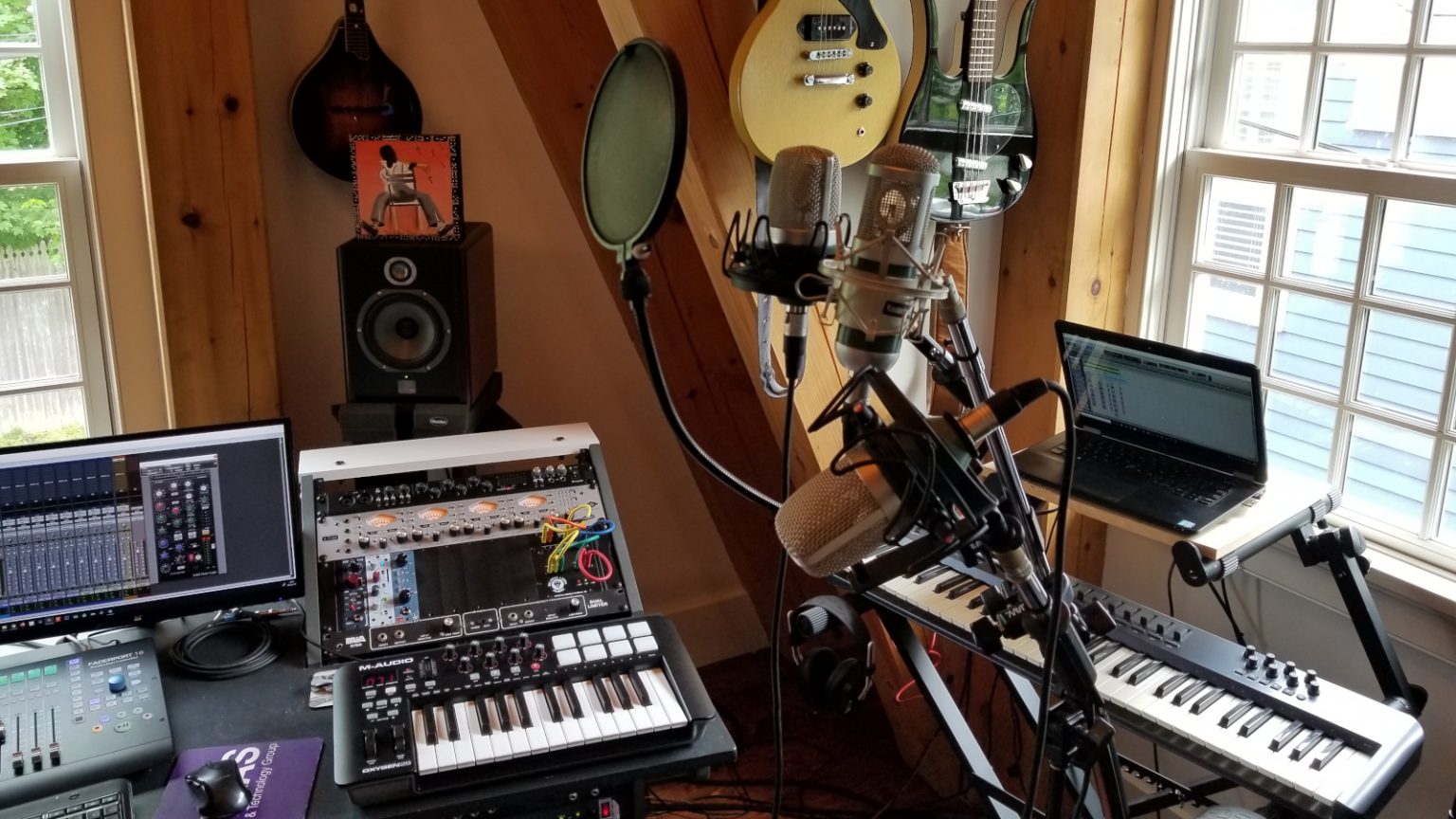
I used the matched pair of modified MXL990 and the modified MXL910. The 990s have the RK12 capsules in them and are very AKG-ish “hi fi” with a flat, extended response. The 910 has a K47 style capsule in it which has that upper midrange edge of a Neumann. One of the 990s is set up low and facing up. This was for the falsetto parts as I do them more easily if my head was angled down a bit (the Bee Gees finger in the ear trick was helping too).
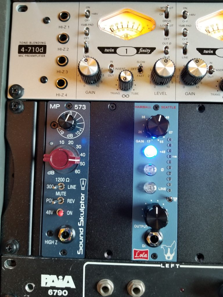
Preamps used were:
- UA 4-710D in half tube/transistor mode with a little of the FET comp,
- Sound Skulptor MP573 Kit
- Rupert Neve Designs 511 (which I have since sold)
MoDs On ThE RuN
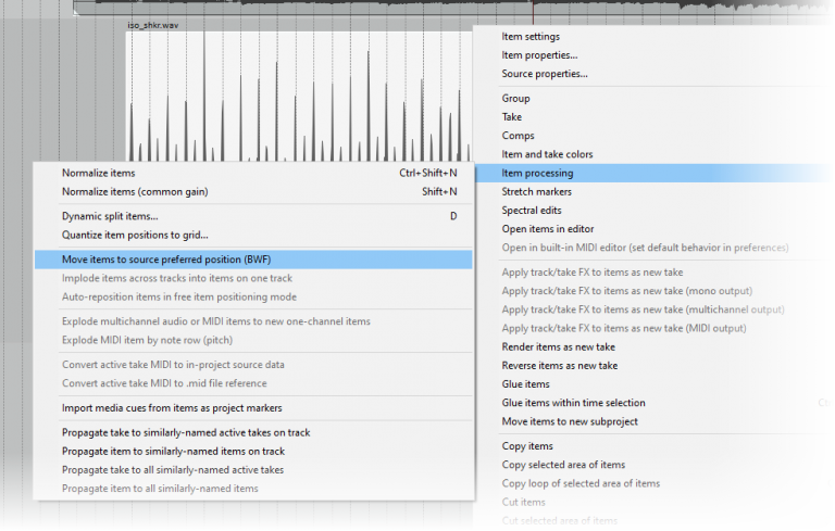
I liked all the tunes very much, but this one was especially fun. It’s a clear nod to The Who and Rick was wondering about getting a Baba O’Riley-ish sequencer on it. The drums were played by the incredible Mike Ricciardi. In addition to being a great drummer, Mike is also an accomplished photographer with a very unique style. To do a sequencer part, I needed to build a tempo map to the reference track provided by Jeff. This turned out to be very easy because Mike is so good!
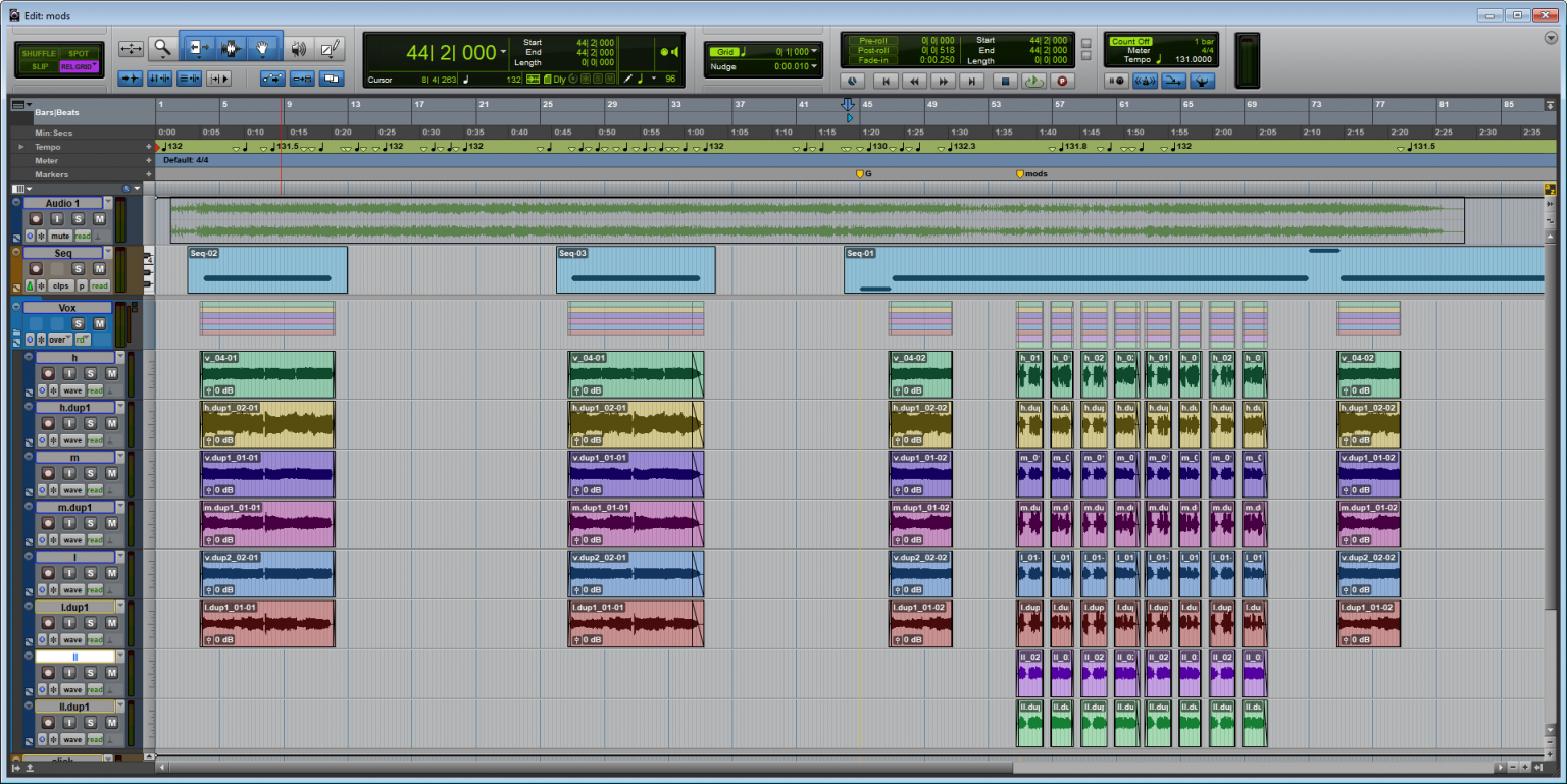
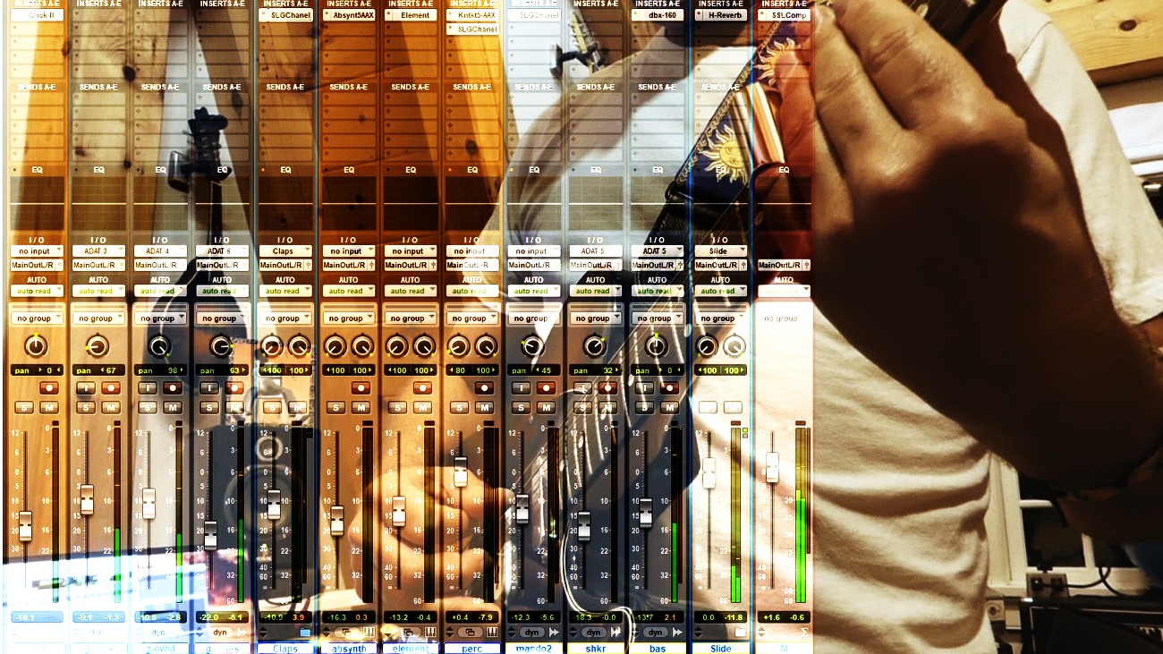
Most of my parts are “Ahhs” and that is what you see where there are six tracks. In the middle, I’m singing eight tracks of “Mods… we are Mods… we are the Mods on the run”. I tend to avoid copy-paste background vocals and prefer to sing each repeated part each time it appears in the song. I may have broke that rule a bit on the falsetto parts because I am still struggling a bit there. When I got a part that worked, I tended to copy those!
For the Sequencer, I used what is becoming one of my favorite synths: Waves Element. I absolutely love this synth. It’s complex enough to do anything, but simple enough to easily program great patches from scratch. It brings me back to my Korg Polysix days. I built a patch I liked, set up a pattern in the built-in sequencer and it played perfectly to the tempo map.
The Result
Here is MoDs On ThE RuN released to youtube. Enjoy Rick’s animations while you listen!

Check out the rest of Rick Iacovelli’s Youtube Channel here. The other tunes and much more of his cool animation are there. Give him a like and a subscribe while you’re at it!
The Other tunes I contributed to are listed here. Vocals on all of them, but a guitar or keyboard here and there as well.
- But I Ain’t Got You
- Wishing Well
- Dandelion Today
Thanks again, Rick for the reason why.